Drill
Press Motor and Tachmeter
4/10/14
I decided to modify my drill press by installing the variable speed 3/4
HP sewing machine motor I discussed in Replacing
My Lathe Motor. I also plan on installing a
MachTach tachometer like the
one I built for the lathe.

The object of this project is my floor model Clausing drill press which
I bought
new in about 1965 or 1966
My first step was to remove the stock motor
and plan the mounting of the new one. As the motor mounts to
a
flat plate, I have a lot of flexibility. After positioning
the
motor to properly align the belt I realized I would need to add a small
extension to the bottom of the cast iron mounting plate and add a new
mounting hole near the top. I will machine a new two step
pulley
similar to the two bottom steps of the stock pulley, to fit the
15mm motor shaft, but for now I am using the cheap 5/8 bore pulley I
bushed to fit using shim stock.

The motor mounting plate provides a lot of flexibility, but did need to
be extended
downward slightly. The new tapped hole in the top center and
the two in the extension
will mount the sewing motor. I could have used an adaptor
plate or board, but decided
to add the aluminum extension instead.

The motor is mounted and a link belt is installed. I tested
it by drilling a 1/2 inch hole
in some hot rolled steel. The only problem I had
was occasional slipping of
the link belt on the motor pulley - the motor never stalled.
I need to remove a link
or two to from the belt to be able to tighten it some. Once I
have the final pulley
built and installed I plan to get the correct length of a standard
belt. They seem to
have better grip with less tension, and I do worry about this tiny
motor's bearings.


For the tachometer input I decided to use magnets and a Hall effect
sensor. The optical pickup is working great on the lathe, but
it
is located
inside
a closed cover and should stay fairly clean. The magnetic
pickup
is much more tolerant of dirt and grime, and in this case, lends itself
better to the configuration of the drill press.
I mounted two magnets in the bottom rim of the quill pulley by
counterboring snug fitting holes and mounting the magnets using a little
J B Weld epoxy. The tachometer will accept up to 60 magnets,
slots, or reflective strips depending on the sensor used. The
only
advantage of using a lot of points is to be able to read lower
RPMs. Two magnets keep the pulley balanced against what ever
effect the
tiny
magnets would have, and will let me read down to 15 RPM . I
cannot see any need to ever run slower than one revolution every
4 seconds!
The sensor which detects each passage of a magnet is a tiny little
thing at less than 3/16 inch wide.
I had a small
problem of an incorrect
part in my tachometer kit, so completion of that is delayed a
bit. I completed all I could then set the tachometer
aside.
In the meantime I am designing the mounting bracket for the
sensor and the control box to hold the tach and the speed control pot.

I machined a mounting block and used JB Weld to mount the
sensor. It and the
control box cover (shown rotated 180 degrees) are placed on the drawing
of the
block. As the sensor is pretty much hidden by the epoxy, I
used a marker to
indicate its centerline for easier alignment.


Clausing was kind to me and provided a 5/16 UNC hole in the perfect
position to mount the sensor block. I did drill the 9/16 dia
hole
down into the center of the head casting. This gave me a
wiring
route to the front of the head where the controls will be mounted with
no
"close
encounters of the belt kind". The AC wiring comes up into the
belt shroud from the back and enters the power box through
existing holes in the front casting. I have a piece of thick
protective
rubber under the cords as they pass over the bottom flange in the rear.

As the original power wire is almost 60 years old, with
badly tarnished copper conductors, I
replaced it with new. Instead of buying just a power cord, I
got an industrial extension cord with
a 3 outlet receptacle. I cut this cord to connect to the
power switch. I now plug the motor and
the tach power supply into this receptacle with a spare slot for the
possible addition of a light, all
controlled by the main power switch.

Originally, the ON/OFF switch was mounted here. I will mount
that
switch on the front of the belt cover casting, directly above.
I started to leave the power switch where it was and mount the new
controls up high. I used the drill press a few times in this
configuration
and almost without fail, I would stop the motor using the power switch
(as I have for decades). Swapping the locations will make it
more
natural to use it correctly, which is to turn the speed dial to
0. The
power switch is turned off only when the session is over.
That is probably the largest disadvantage of using this
motor.
You cannot set a speed and just turn it on and off. If you
try to
start
with a speed of over several hundred RPM motor speed, It returns an
error message. In other applications another major problem is
the
way the motor reverses. Using the two buttons on the motor
controller, you enter a menu and step through several items until you
reach the number representing direction. You manipulate it to
the
new direction and wait 5 seconds to exit the menu. This is
not a problem on the drill press, as I never intend to run it backwards.

I have now mounted the boxes. The lower box will have a
labeled
overlay once I install the MachTach and the upper box will house
the power switch. I am running the power cables through the
belt
housing and feed the power box from behind for concealed wiring.
And yes, I did clean up the nameplate and re-lacquer it. It
was really
grungy as seen in the first picture.

This is the finished Project. The part for the tachometer
came in and it took little time to
finish up. The power switch is handy, but not so much that I
hit it by mistake. The tach
and speed control are at a good usable height. I am pleased
with the outcome! As it is
set up now with the single level motor pulley, I can run from about 50
to about 1600 RPM.
Update
of 12/5/2015
New drive
For over a year and a half
now, the drill press has been working great, with one exception.
Recently, on several occasions when the drill press was
running
relatively slowly, it would spontaneously speed up to what appeared to
be the maximum speed for a moment, then it would resume at the set
speed. It might do this several times
during a
project, or not at all. No damage has been caused by this
(except
to my nerves), but if I were doing something delicate, the results
could be disastrous! (Think tapping!) Without any
documentation on the controller, and with no warranty due to my
modifications, I have little chance of correcting the cause of this
problem.
Dealer's Electric, the company from which I bought my
Lathe and my Mill VFDs had a very good price on a package of a 1/3 HP 3
phase motor and the same model VFD I have on my other two machines.
For Black Friday they offered $10 shipping. This is
about
$50 less than normal, and for well under $200 delivered, I ordered the
package. As I write this on a Saturday 12/5, it is in
Prescott Valley,
to be delivered on Monday. Besides reliability there are a
couple
other advantages to changing: I will no longer have to turn
the
speed to 0 to stop the spindle. I can set a speed and use a
switch to turn it on and off. I will also have an easily
switched
reverse capability. This will be seldom used, but is an
option I
will like having. The motor frame type is identical with the
original motor, so will bolt to the same mounting holes and accept the
original pulley perfectly.
To
mount the VFD and the
new controls, I mounted a plastic junction box on the left side of the
drill press head. This box will contain all the new
components to
control the motor speed and direction. The top electrical box
I
previously
installed with the main power switch will be removed and the location
will revert to the original
configuration. The box with my MachTach and the speed
potentiometer will remain unchanged.

The partially machined box is test mounted on the drill press.
After
finishing the machining of the control box and painting it, I installed
all the components and wired them.
The box contains the master power switch and the
Forward-Off-Reverse switch on the front panel, the VFD front face on
the left panel, and a duplex outlet, switched by the master switch on
the rear panel. There are also a fuse, a terminal strip, and
electrical cables. I encountered one problem: the box was not
quite deep enough for the VFD to mount and keep all the control wires
inside the cover. I solved this by machining a hole for the
VFD
in the bottom of the box. I covered the outside of this hole
with
a piece of sheet metal and mounted the VFD to this metal.
This
lowered the VFD by about 1/4 inch and almost cleared the wires from the
inside of the cover. Thinning the cover where the wires
exited
gave plenty of clearance.
Operation is slightly different from my other
machines. For this application I decided that a single twist
switch for forward, off, and reverse operation would be most practical.
I will occasionally do power tapping on this machine, and
this
type switch is the most useful for a quick reverse of the motor at the
bottom of the tapped hole. My other two speed controlled
machines
have a switch to determine direction and separate start and stop push
buttons. Fortunately, the VFD is flexible enough to accept
almost any control system you might desire.

The control box has been all wired including the line cord and wire
connecting the motor.


The motor mounted exactly like the original one,
with no modifications needed. The rear
of the control box contains a
duplex outlet for the MachTach power supply and a possible future light.

The finished installation shows the new box on the left and the
original tach box on the front.
The new box contains the master power switch and the
Forward-Off-Reverse switch. The
tach box carried over from the first modification contains the MachTach
and the speed control knob
.
Mods of
3/25/2016 Tapping Provisions
The
new motor and drive have been working great, with one exception:
I have used this new setup several times for power tapping holes.
I set the spindle speed very low, allow it to tap the hole, then
at the bottom of the hole I reverse the spindle to withdraw the tap.
The problem is that I don't have three hands! I need one to
hold the workpiece in place, one for the feed lever, then another to
reverse the motor at the bottom of the feed. I read recently on
one of the machine tool forums of a fellow who had the same problem,
and solved it by adding a foot pedal to reverse the motor. Bingo!
Over
the years I have collected 3 different electric foot pedals, so I
started thinking about how to control the motor direction with one.
I decided that instead of my panel switch selecting "FORWARD,
OFF, and REVERSE" I would have it select "DRILL, OFF, and TAP".
The "DRILL" position would simply be the same as the old "FORWARD"
command, "OFF" would of course still be "OFF", but the "TAP" position
would now route the controls through a relay which would control the
direction on command of the foot pedal. I initially was going to
have the "TAP" position run forward until I pressed the pedal, which
would change it to reverse. After thinking about this, I decided
to make the "TAP" position run it in reverse, letting the pedal change
it to forward. My reasoning for this was that if I should want to
run the machine in reverse for any reason, the "TAP" position would do
this automatically. For tapping, as I am ready to feed the tap, I
press on the pedal until I want to reverse it, then I release it.
Going
through my junk boxes, I found a multi-pole relay with a 6 volt coil,
my pedal switch, and a 6 volt "wall wart" type power supply. I
had previously used this power supply on my electric truck and later
replaced it. It had wires coming from the case for both the
115 volt
input and the 6 volt output. I did replace these wires to get the
length and colors I wanted for this project. I
used Velcro to mount the supply in a space barely large
enough to the left of the VFD. I wired the relay to
parallel two sets of contact for increased reliability, then made a
small mount which I Velcro'd to the bottom of the case. I added
a connector to the bottom of the box to attach the foot pedal.
It all works fine now, and the next time I decide to power tap
some holes, it should be quite easy.
Note of 10/17/2020: I
have power tapped many holes since completing the above modification
and it works wonderfully! I will not use it for tight bottom
tapping, but will start with this machine and stop well clear of the
bottom. I then complete the tapping manually where I can feel the
bottom. For through holes or shallow threads in deep holes I have
no hesitation of using this power tapping capability.
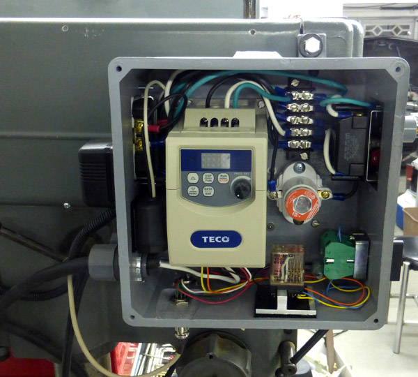
Here is the finished control box after adding my tapping mods.
The 6 volt power supply is just to the left of the
VFD ; The control relay is in a socket mounted to an aluminum mounting
base just to the right of the VFD. The
connector which attaches the pedal is in line with the MachTach
connector and toward the rear of the box.
GO BACK TO "Machine Shop
Projects"
Richard S. Mason 4/2014