Home Trips Motor Home
Projects
House Projects  Machine Shop
Projects
Automotive
Projects
Early Computer
Days
About


Adding a Tachometer to my Lathe


February 2014

In the early 70's I added a variable speed split-pulley drive to my lathe to provide variable speeds.  One problem with this is that I really never know just how fast the lathe is running.  There are a couple of low cost digital tachometers available for machine tools.  I looked at the available ones and narrowed it down to the Mach Tach.  This is a true kit where you build it from a bare circuit board.  They offer complete kits, kits containing only the circuit board and the custom chip, and the custom chip by itself.  They offer both full size and half size models.  The half size model splits the circuit board in two and is built with the two halves stacked.  You can choose red or green displays.  Also available are a number of accessories such as power transformers, optical and magnetic speed sensors, a case, extra display lenses, etc.

The instrument will accept reflective optical sensors (supplied standard), Hall effect magnetic sensors, inductive sensors, or direct optical sensors which detect slots in a disk.  Actually, it can be used with any sensor which provides a TTL level output (0 & 5 volts).  It can be programmed for 1 to 60 pulses per revolution to allow for many reflectors, magnets, or slots for very high resolution at low speeds.  The speed range is 0 to 9999 RPM or SFM (surface feet per minute).  To use the SFM function, you need to enter a work diameter for a lathe, a cutter diameter for a mill, or a drive wheel diameter for a band saw.

Progress:

I have ordered a full size kit  with green displays, a Hall effect magnetic sensor, and a case for the unit.  The total was about $70.  I expect to receive the kit within the next couple of days.


Pictures from the Mach Tach website show what I have coming.  The left shows the tach assembled in the case they offer.  Mine will
have green displays.  You can also build it into an existing control cabinet.  The picture of the circuit board shows what is involved.  The
horizontal line in the middle is where the board is cut for the half size version.  You can also cut off the end of the top half to remotely
mount the encoder/pushbutton.


As I said earlier, this is really a kit.  I will be doing the total build.  Shades of my
early computer days!


This is an ideal area on my lathe to mount either the reflective strips for the optical
sensor, or a ring with magnets for the Hall effect sensor.  There are even 1/4-20
holes available in the lathe to mount the sensor.
2/4/14
OK, my kit just arrived.  I set up a workstation in my office (much warmer than my shop!), printed out several sheets from the on-line manual and started inserting and soldering components.  It took a little over an hour to build the board, then about 15 or 20 minutes to clean the flux off the board using rubbing alcohol.  I had made a trip into Prescott Valley to the Radio Shack to pick up some flux remover, which I have bought in years past with no problem.  The clerk said they didn't carry it, and checked their website with none there either.  I'm afraid that Radio Shack has degraded pretty much to a cell phone store!  The rubbing alcohol  is much slower and requires a lot more scrubbing with a toothbrush, but it does a good job.  My board is spic and span with no flux residue left.

I plugged in the custom IC and powered it up.  It all seems to work!


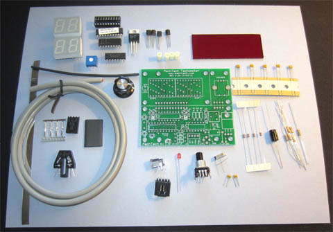
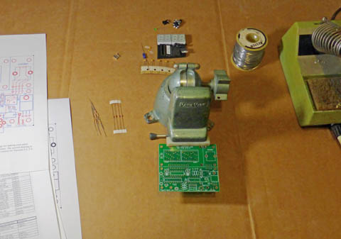
I'm ready to start building the board.  The circuit board is top quality, with solder
mask and silk screened legends.  the pads are reflow solder coated for great soldering.


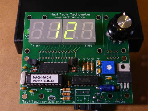
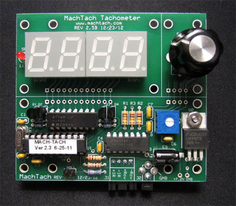
On the left is my finished board, just powered up for the first time.  All the preliminary checks work correctly.

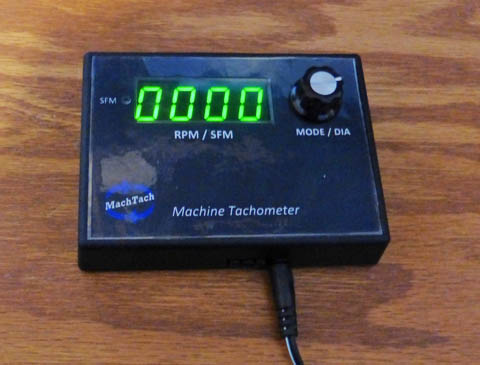
To install it in the case, I had to cut the  openings in the case for the display, the SFM LED, and the control knob.  I cut the green
plexiglass lens to be a tight fit in the display opening and glued it in flush to the top.  I trimmed and attached the front panel legend
to the box with double sided scotch tape.  The board then mounted inside and is shown on the right.


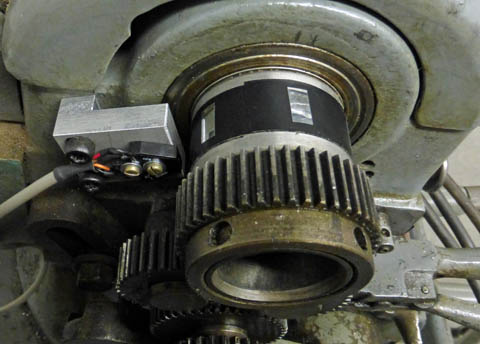
For the light reflecting surface I wrapped the spindle shaft with black electrical
tape and placed 6 pieces of reflective tape equally spaced on it.  The sensor is
mounted on a simple bracket using tapped holes already in the lathe.  After setting
up the sensor, I had to adjust a trim pot to ensure that when the sensor points
to black, a test point is more than 4 volts, and pointing to the silver it is less than
1 volt.  Both conditions are now met with a good margin.


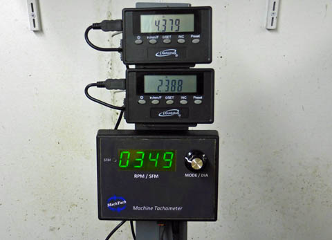
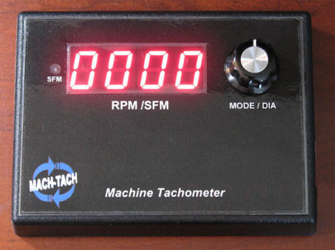
I have installed the display on my temporary DRO display mount for easy visibility.
I checked the readings against a hand held tachometer at a couple of different
speeds and they matched almost exactly.


The tach has been working fine, but I have noticed that there is a 1 or 2 RPM shift in the readings as it updates each second.  While this is totally acceptable as far as accuracy is concerned, I thought I would try to improve it.  The tach calculates RPM by measuring the time between adjacent strips and averaging these times for 1 second.  While this provides a very stable output, if there is a variation in the times between strips, the average can vary slightly depending which strip starts the averaging.

I decided to correct the problem.  I found that my original efforts to place the strips equally were not very successful.  A couple of my strips were significantly out of position.  I set up a 60 tooth gear on a shaft in my 3 jaw chuck and marked between each group of 10 teeth.  Using an old lathe tool as a stop, I was able to very accurately rotate it exactly 1/6 of a turn at a 
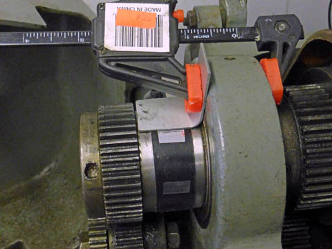
time.  I clamped a metal strip on the tail of my spindle to allow me to place the strips very accurately.  I would estimate that each strip is now within about .010 inch of being equally spaced.  Before, I had one that was a full 1/4 inch out of position.


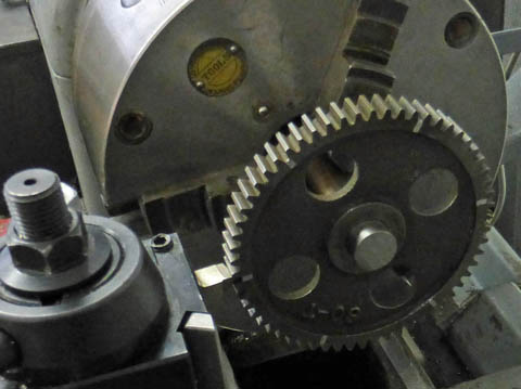
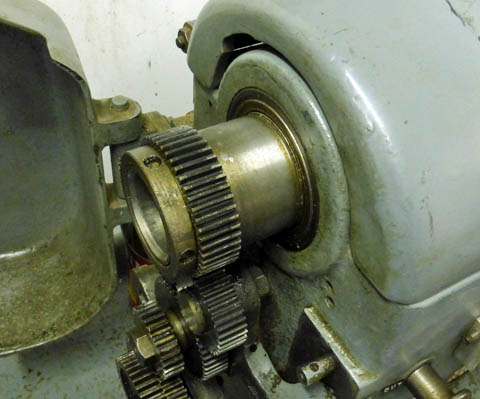
On the left is the 60 tooth gear I am using to accurately index the spindle 60 degrees at a time.

On the right you can see my guide to help me place the strips accurately.


After I corrected the misplaced strips (actually only 2 of them) I tried it and there was absolutely no jitter.  The readings were totally stable.  I am very pleased!


Richard S. Mason  2/2014