Replacing My Lathe Motor and adding a VFD
February 2014
My dad bought this lathe when it was 7 or 8 years old in 1965. Unfortunately he was only able to enjoy it for about 3 years, then I inherited it. The motor in it is well over 50 years old, and has, until recently, performed flawlessly. A couple of months ago I started getting a loud squeal which I finally traced to the shaft end of the motor. I pulled the motor, opened it up, and verified that the bearing was very rough. After much flooding with light motor oil, enough wicked past the shields to temporarily quiet the bearing. I guess it is time to either totally overhaul the motor by replacing the bearings, the starter switch, the capacitor, and any other wearable parts. Or I could replace the motor with a similar new one. Or I could replace it with an upgraded motor.
Interesting experiment
More as an experiment than a serious proposal I decided to try a sewing machine motor to drive the lathe. No, it's not your mother's Singer motor, but a new line of powerful motors designed to run industrial sewing machines. For decades these machines have been powered by a continuously running motor which is connected to the machine by a clutch. These are inefficient, noisy, and difficult to adjust so they can be started smoothly and controlled accurately. Recently a new breed of these motors has emerged. They are servo motors which are controlled by electronic drives. They are made in both a brush type motor and brushless. They are directly belted to the machine with no clutches, and they start and stop as needed. They are very powerful and can be run from just barely turning to speeds up to about 4500 rpm. I really don't know where they got the term "servo" motors, as these are not positioning motors, but continuously running traction motors, nonetheless they are a tremendous improvement in efficiency, noise, and controllability.
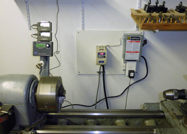
I recently bought one of these motors to experiment with in my shop. I bought a Consew CS1000 brushless motor. It is rated at 3/4 HP and runs from 0 to 4500 RPM. As received, it was controlled by a spring loaded lever which connected to the machine treadle in its sewing use. This lever moved a blade into an opto-coupler interrupting the light beam from an LED to an optosensor. As the blade cut off more light, the motor sped up. I replaced the opto-coupler with a potentiometer for more convenient use for my purposes.
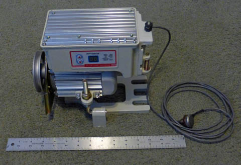
This is the sewing machine motor that puts out 3/4 HP. The electronics are in the
box on the top and have a display of the current RPM (in hundreds - 2 digits).
It also is the display for a simple menu system to set up the various parameters.
The motor itself is remarkably small for its power.
I attacked my
lathe and pulled out the
motor and the variable speed drive I installed in the early
'70s.
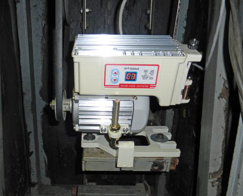
I then installed my sewing machine motor. Installation was a
breeze. I placed it on the center shelf where my split pulley
used to be. Two of the large slots in the motor base
encompassed
existing tapped holes, and by adjusting the heights, the belt I
previously used on the upper half of the split pulley fit fine.
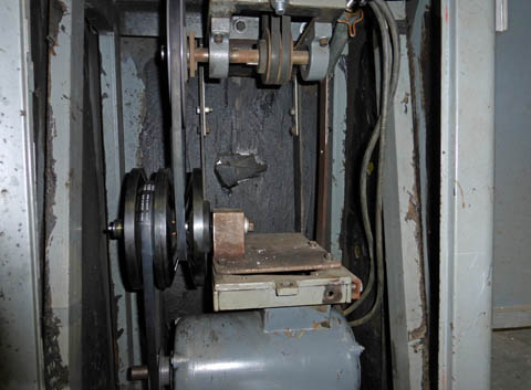
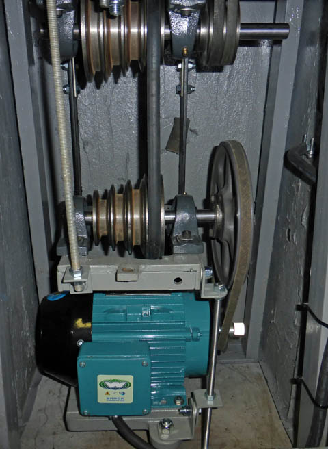
On the left is the variable speed drive I installed in the early '70s. the center shelf is raised and lowered by turning a handle on the front of the lathe.
The change in belt tensions forces the center of the pulley to slide and change the ratios. The double V-belts at the top go up to drive the spindle.
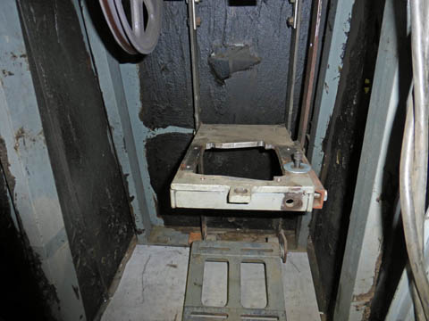
On the right I have removed the motor and the variable speed components.
I mounted the sewing motor on the center shelf. I was able to turn the old speed
change crank to adjust the belt tension. I ended up putting a somewhat smaller
pulley on the motor shaft. Of course the motor shaft is metric (15mm) so
I had to bush a 5/8 bore pulley. I actually used a wrap of .017 thick shim
stock, which created a light press fit, but it went together fine.
On the left is the variable speed drive I installed in the early '70s. the center shelf is raised and lowered by turning a handle on the front of the lathe.
The change in belt tensions forces the center of the pulley to slide and change the ratios. The double V-belts at the top go up to drive the spindle.
On the right I have removed the motor and the variable speed components.
I mounted the sewing motor on the center shelf. I was able to turn the old speed
change crank to adjust the belt tension. I ended up putting a somewhat smaller
pulley on the motor shaft. Of course the motor shaft is metric (15mm) so
I had to bush a 5/8 bore pulley. I actually used a wrap of .017 thick shim
stock, which created a light press fit, but it went together fine.
I am amazed at
the performance of this
little motor. It will drive the spindle from about 35 RPM to
about 1100 RPM just by turning the knob on the pot. In back
gear
it will run from less than 5 RPM (the lowest my tach reads with
6
reflective segments per revolution) - that's 1 turn every 12 seconds -
to somewhere around 150 RPM.
I didn't
crank the motor to full speed in back gear. What really
amazed me
was that at 35 RPM in direct drive I could not stop the spindle by
pressing my hand on my 6 1/2 inch 3 jaw chuck as hard as I could
press! I have not actually done any machining yet, but all
indications are that it would actually work pretty well for almost all
my work,
I am not serious about leaving this motor installed on my lathe. I really think I need a little more "serious" power source, but I think this motor would work great for my drill press.
Decision
What I did decide, though, is to replace my old motor with a 3 phase motor and a VFD (variable frequency drive). A VFD takes single phase or 3 phase power, in my case it will be 115 volt single phase power from a wall plug, and converts it into 220 volt 3 phase power. The big advantage is that it will output from 0 frequency to whatever top frequency you program. Most motor manufacturers recommend not going over 150% of the nameplate rating, and you risk overheating the motor at very low speeds where the built in fan is ineffective, unless you add an external fan. This means that for a 1725 RPM motor, you can run it from near 0 to around 2600 RPM, producing full torque up to about 1800 RPM with a drop in torque, but constant horsepower above that. In summary, this setup and the sewing motor are very similar. Both have a VFD (built in on the sewing motor) and a multi phase motor which can vary its speed with the turn of a pot. My new setup is of a more substantial construction and has higher horsepower, but a lower overall speed range. Actually the VFD has the capability to run a motor faster than the 4500 RPM of the sewing motor, but I would not trust my motor to hold together at 5700 RPM, the maximum the drive could turn it.
I decided to go the 3 phase motor/ VFD route after comparing the price/value ratio for new standard motors, overhauling my existing motor, and a super deal on a VFD and 1 HP 3 phase motor from Dealer's Electric. They have a Teco/Westinghouse VFD, which is a well known, quality brand, coupled with a new 3 phase 1 HP, fully enclosed motor for under $200! OK, it's only a penny under, but it is under. Of course the shipping really gets you! I am excited to see how this new system works. Everyone who has a VFD system seems to rave about it.
Setback!
While I was preparing for my new motor, I removed the top countershaft to make sure the pillow block bearings were OK. What I found was that one bearing was very rough, and had obviously seized up at some time. The shaft under the bearing was badly worn. I just ordered all new pillow block bearings and a length of 3/4 keyed shafting to totally replace these parts. The pulleys are still fine.
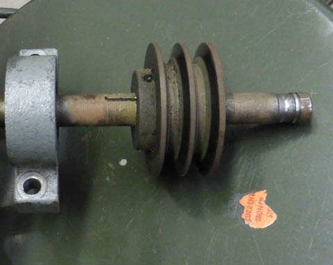
The end of this shaft, where the other pillow block bearing was, shows bad
wear where the bearing must have seized up at some time. I have ordered
all new parts.
2/11/14
The Law of Multiplying Tools
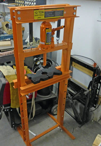
As is so often the case with tasks like this, I will start a project and pretty soon I find a problem. I try to fix the problem and find I cannot without making or buying yet another tool. In this case it was a defective pillow block on the countershaft. When I tried to remove the pulleys and bearings from the shaft with the tools at hand, I couldn't. I needed to press the old parts off the shaft so I can use the pulleys on the new assembly, but my tiny arbor press does not even begin to have the size capacity, even if it has the force capacity, which it probably does not. I tried prying with bars and levers without success. I was afraid to use a lot of force for fear of breaking a pulley flange. The bottom line is that I went to Harbor Freight Tools, with a 25% off coupon in hand, and bought a 12 ton shop press for under $100. After about 30 minutes of assembly putting the press together, I successfully disassembled all the parts from my shafts in just a few minutes. It works great! I have had my eye on this press for a long time, but needed a "special event" to trigger my purchase.
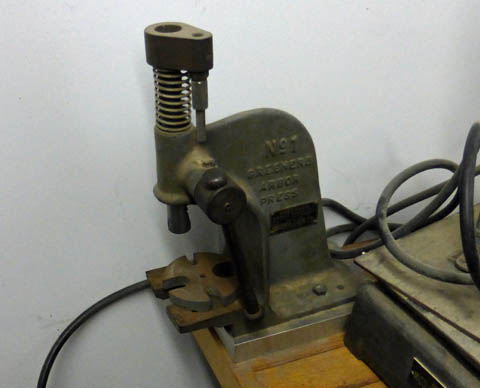
My little arbor press has a maximum height capacity of 4 inches with a throat depth of 3 inches. It is very restricted to the work it
can handle. However, the price was right!
My new shop press has a 12 ton load limit with very large height and depth capacities. And it's price wasn't all that bad!
Motor and VFD arrive! (2/11/14)
A short while ago my new motor and VFD arrived. I have opened them, but not tried them out yet. They look great!
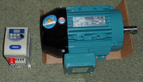
Here is the new 1 HP 3 phase motor for my lathe, and the Variable Frequency Drive (VFD) to control
it. I think it is amazing that such a tiny control box can handle all the power for that huge motor, as well
as varying the speed from about 0 to 3 1/3 times the nameplate speed (although most motors should not
be run that fast).
2/13/14
A momentary scare!
I tried out the motor and VFD today. I used a 10 foot length of 4 conductor 14 ga wire I bought for this job. It is longer than I think I will need, and one gauge heavier (all that was available), but I will cut it down after I determine my exact requirements. After connecting the motor and a line cord to the VFD, I carefully plugged it in and the VFD lit up exactly as the manual said it would showing the line voltage for a few seconds, then the initial frequency setting of 5 Hz.. I then pressed RUN and the motor started very slowly. I then slowly increased the speed. At about 13 Hz, there was a loud clunk and everything stopped. I reconfirmed my previously double checked wiring and tried to figure out what happened. As a test, I turned on my bench power supply to see if I had any power, and had none. I then discovered the GFCI had tripped. With further testing I found that whenever I reached the 12 to 13 Hz range, the GFCI tripped. It was too late to call the supplier tonight, but figured I would first thing in the morning.
When I came in to my office, I decided to Google "VFD GFCI". I got many pages of hits, all of which related problems trying to run a VFD on a GFCI protected circuit. It seems that the high frequency switching in the pulse width modulated voltage control sends all kinds of high frequency noise through the wiring and confuses the GFCI into thinking there is an imbalance in the line, causing it to trip. I plugged into a non-GFCI protected circuit and everything worked as the manual said it would. WHEW!
Cleaning and installing
I cleaned up the drive compartment under the lathe. It looked terrible! It was dirty, and in an effort to quiet the resonance of the sheet metal panels surrounding the drive, my dad had painted black undercoating to help dampen the vibrations. This caused it to look dirty with large areas of black on gray. I removed all the drive mounting trays and their support frame. I then cleaned and painted the interior of the cabinet and all the parts I removed.
I used my CAD program to lay out the new arrangement of the drive components. The location of the twin v-belt drive to the spindle required me to move the mounting frame to the left of its current position. (I had moved it to the right when I installed the variable speed drive). I plan on re-installing the original step pulleys in place of the variable speed pulley. As I never throw anything away (I actually do occasionally), I still had all the parts I took out in the early 70's. Even though I am installing a variable speed VFD controlled motor, I would like to be able to choose the basic ratio. I can also move the large pulley up to the top countershaft and drive it directly from the motor, bypassing the step pulleys and the extra belt. I think this gives me all the flexibility I need.
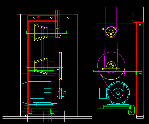
I don't have any records of the drive configuration before I installed the variable pulley in the early 70's,
(and my aging memory doesn't help a lot) but I think it was somewhat like this. I have moved the
mounting frame to the left from where it was for the last 40 years, but about an inch to the right of its
original location. This gives me minimum shaft overhang of the spindle drive pulley.
I can easily move the 8 inch pulley up to the top countershaft and drive it directly from the motor, eliminating
one belt stage. I may desire to do this after gaining some experience and selecting the best ratio.
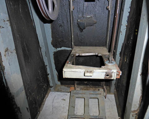
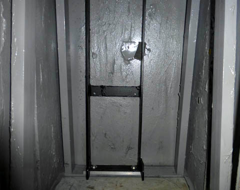
The original cabinet lacked much in "curb appeal". Repainting the cabinet interior and the contents will help a lot. On the right you
see the mounting frame installed after moving it several inches to the left. This will allow the various components to fit and align with
the spindle belts which are really the only hard and fast location. The ugly splotch in the center of the wall is a stack of rubber pieces
my dad glued to jam between the sheet metal back wall and the frame (it used to be 1 inch further left) to dampen vibrations. I added
a couple pieces to do the same, but later found it was no longer necessary.
It is obvious to me that this mounting frame and the two upper shelves are not original Logan parts. Someone, probably my dad, modified
the factory configuration. I cannot figure out the original Logan setup, as any pictures I have found on the web show parts mounted on the
vertical frame members. There are no mounting holes in my frame.
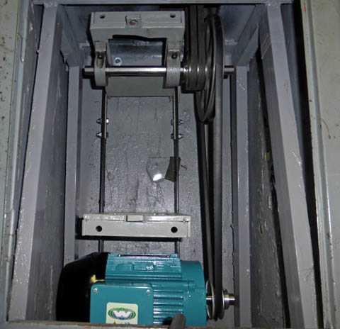
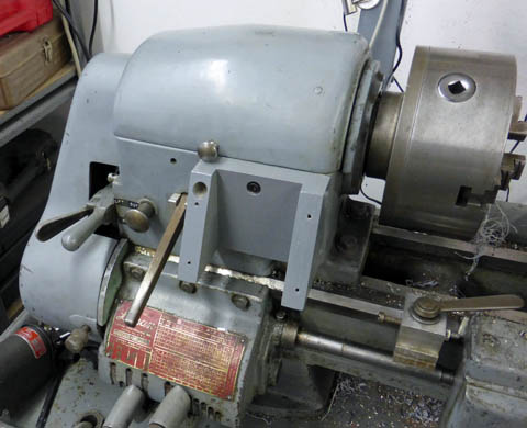
I mounted the motor and temporarily installed the two best of the original pillow
blocks along with the pulleys as a temporary setup. I had to slot the mounting
holes of the motor slightly to align with the cast mounting slots in the bottom shelf.
I cannot believe how quietly my lathe runs now! There is none of the low frequency
rumble that used to echo in the sheet metal whenever the old motor was running.
As it is currently belted, I can run from about 50 RPM to about 900 RPM spindle
speed in direct drive with the allowable frequency range of the VFD programmed from
5 Hz to 90Hz. Back gear speeds are 1/6 of these. The addition of the step pulleys will
allow me to adjust these speeds up or down.
2/20/14
My pillow blocks just arrived. Did you know you can buy pillow block bearings from Amazon? It only took a couple of hours to get my two countershafts all set up. I had one new belt that worked for the cone pulley stage and a temporary 20 to 50 year old belt for the motor. It works, but will be replaced soon.
Here is my fully assembled drive system. It includes 4 new pillow block bearings and
new shafting. The cone pulleys have been out of commission for over 40 years, but
are still in excellent shape. All 3 belt tensioning rods have been added, completing
the mechanical part of this project.
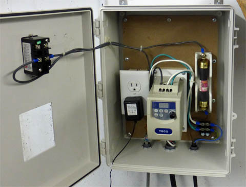
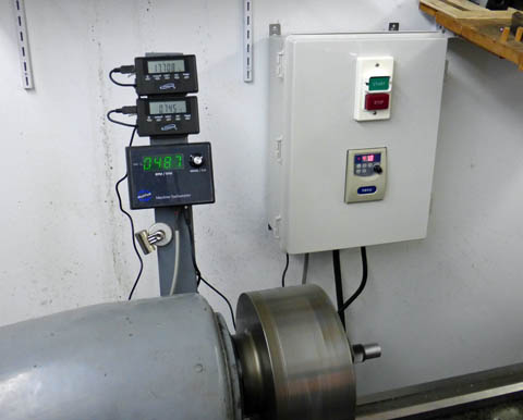
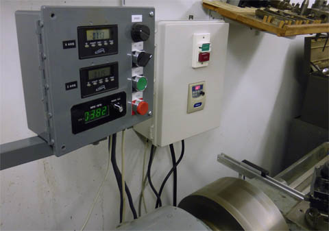
While I was waiting for my pillow blocks to be delivered I wired up the VFD and a fused disconnect box. I plan to get an enclosure for the VFD as there is little protection the way it is designed. They are all supposed to be installed in larger boxes, but many people don't do that, and just mount the VFD by itself. While I was at it, I wired my existing drum switch to control the motor in the same manner as when it was connected to my previous motor. Now instead of controlling full motor voltage and current, it only controls a logic level of a few milliamps or less. In looking for a shielded multi-conductor cable (I only need 3 wires for this function) I found a 10 foot Centronics type printer cable in my garage. I have not had a printer using a Centronics connector for at least a decade, so I lopped off one connector, and sure enough, the cable was shielded. As I said I only need 3 conductors - this had about 25! They were small at around 24 ga. I also kept several other wires as spares and cut off the rest. I also had a serial cable that was shielded with a lot fewer conductors, but it was less than 3/16 inch diameter so I was afraid of it getting snagged or damaged. The cable I used is about 3/8 diameter, and will not easily get pinched between parts.
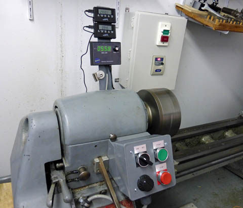
I installed the VFD and the disconnect box on a board, leaving room for the enclosure I will be adding.
I figured this was a good way to mount the items as well as allowing me to wire most of it at my bench.
The duplex outlet is switched on and off with the main lathe power, and will be used for my tach and
possibly for an AC power supply for my DRO's. This picture shows the spindle running at 265 RPM
at a frequency of 35.0 Hz.
I decided to temporarily wire up my existing drum switch to control the on/off/reverse functions as that is what I
instinctively reach for, and I have it now. I will probably change it to start and stop buttons and a reverse switch shortly, it
is a simple matter. At this time, I am using the pot on the drive unit to control my speed. I have a
10k linear Allen Bradley pot just waiting for me to mount and wire in, but at this time, the VFD is as
handy as any place I have to mount it.
So far, I am very pleased with the ease of control, the speed range I can set, and especially the quiet running.
Change of Plans 2/26/14
I ended up ordering a somewhat larger enclosure than I had originally planned. The VFD manual indicated I needed more space around the unit for proper cooling. After seeing the size of my new enclosure I decided it was foolish to have all the extra ugly gear for disconnect and extra outlet showing, I could incorporate all that into the enclosure itself. I ordered a two pushbutton machinery type on/off switch and found a surplus porcelain cartridge fuse holder and the class fuse the VFD manufacturer recommended. I decided to mount the VFD so the front panel protrudes slightly through the front cover of the box. This still gives me access to the buttons and knob for setup and control, and lets me see the output frequency, while protecting it from debris and accidental electrical contact.
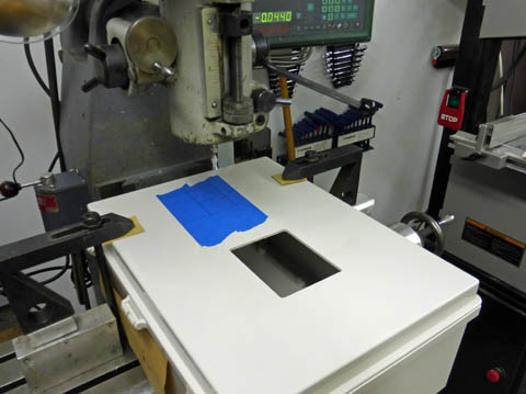
I cut the holes for the VFD and the on/off switch using my mill. The large box is very
awkward to handle and setup. When I cut the large hole I had to cut half from one
side, then turn the box around to cut the other. I guess I need a larger mill! Or I
could have extended the head of the mill out further, but then I would be faced
with a lengthy alignment process to put it back accurately.
I have mounted the assembled box. It looks so much better than my previous
kludge! The on/off switch just came in and I was able to finish this project.
Relook at the mechanics (3/6/14)
I have noticed that it is very hard to adjust the belt from the motor to the lower step pulley shaft, and that I had to get an exact length belt for it to work. Looking at the geometry of the motor, its pivot point and the location of the pulleys I saw that the motor pulley moved almost at right angles to the shaft center lines, meaning that moving the motor a lot, tightened or loosened the belt very little. This is a fatal situation to my plans of an eccentric lever loosening the step pulley belt enough to change ratios, as the motor belt would not let the motor lift.
I decided to totally remount the motor, hanging it from the middle shelf and relocating the pivot to be level with the motor shaft for maximum adjustability of the belt. Also, when I swing the middle shelf to loosen the step belt, the motor just moves with it with no relative motion between the two.
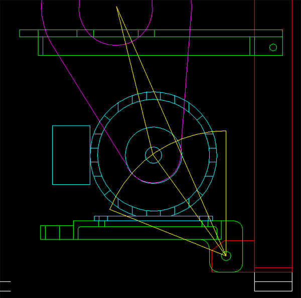
On the left you can see that the pivot point is almost in line with the pulleys, so that there is very little change in the belt tension for a large movement of the motor. In
fact, if the motor is lifted more than a few degrees, the belt starts tightening again.
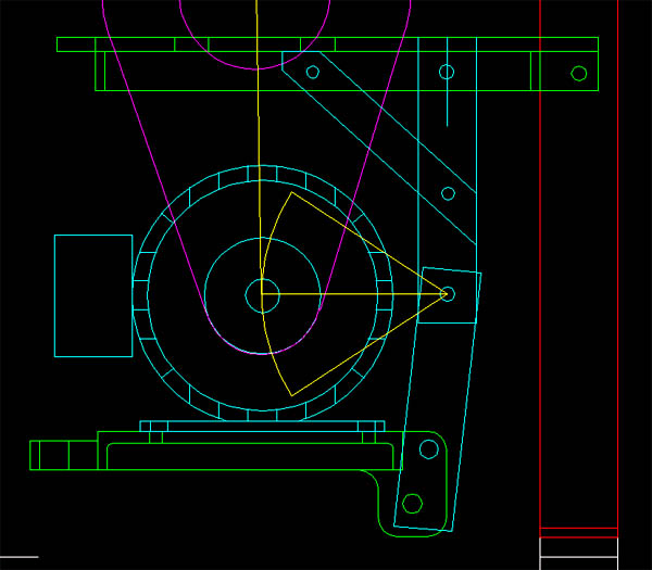
On the right, the pivot point has been moved even with the motor centerline and now a small movement of the motor will have a large effect on the belt tightness.
Also, when I move the middle shelf (top in this diagram) to adjust the step pulley belt, the motor will now swing with it, with no effect on its belt tension.
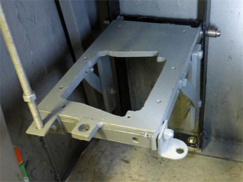
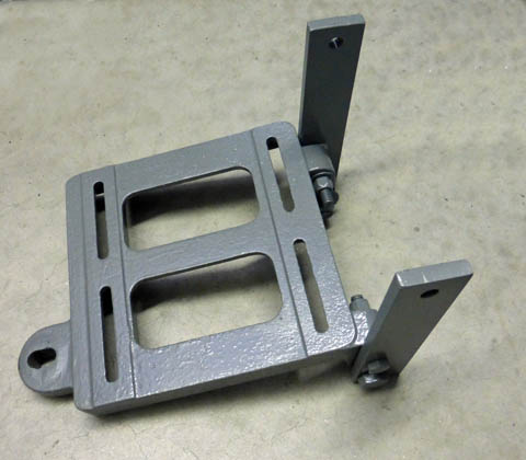
On the left you can see the center shelf with the added brackets hanging down to provide a pivot for the motor.
On the right is the motor shelf with two brackets going up to complete the pivoting mount.
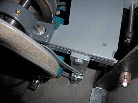
I tried really hard to get a good picture of the final assembly. It just cannot be seen
from outside the cabinet. I finally got this shot by holding the camera at arm's length
inside the cabinet and shooting blind (one of several I tried). It at least shows one side
of the combined brackets and the new raised pivot point.
Control changes
As I stated above, I decided to keep the drum switch as my main control for the time being. It works well, but I really want to do it right. I have ordered start and stop pushbuttons and a reversing switch. The VFD will readily accommodate these. I bought a plastic outdoor double outlet box which should have enough room to mount these new controls along with a speed controlling potentiometer. The box should fit OK on the front of the headstock where the current drum switch is mounted.
March 19, 2014
Buttons and switches
I milled out all the excess studs and the inner part of the conduit inlet from the outlet box, mounted the buttons, switch, and potentiometer. I made a hard-wood mount on the front of the lathe, attached the control box, and wired it all up. A couple of changed function codes on the VFD, and it all worked correctly.
I made a mount from oak which attaches using the same holes which held the
drum switch.
The finished control box is mounted and wired. You set the direction of the spindle
using the Forward/Reverse switch on the upper left. You then press the green
start switch and it runs. You control the speed using the knob on the lower left.
To stop, you press the red stop button.
I am not serious about leaving this motor installed on my lathe. I really think I need a little more "serious" power source, but I think this motor would work great for my drill press.
Decision
What I did decide, though, is to replace my old motor with a 3 phase motor and a VFD (variable frequency drive). A VFD takes single phase or 3 phase power, in my case it will be 115 volt single phase power from a wall plug, and converts it into 220 volt 3 phase power. The big advantage is that it will output from 0 frequency to whatever top frequency you program. Most motor manufacturers recommend not going over 150% of the nameplate rating, and you risk overheating the motor at very low speeds where the built in fan is ineffective, unless you add an external fan. This means that for a 1725 RPM motor, you can run it from near 0 to around 2600 RPM, producing full torque up to about 1800 RPM with a drop in torque, but constant horsepower above that. In summary, this setup and the sewing motor are very similar. Both have a VFD (built in on the sewing motor) and a multi phase motor which can vary its speed with the turn of a pot. My new setup is of a more substantial construction and has higher horsepower, but a lower overall speed range. Actually the VFD has the capability to run a motor faster than the 4500 RPM of the sewing motor, but I would not trust my motor to hold together at 5700 RPM, the maximum the drive could turn it.
I decided to go the 3 phase motor/ VFD route after comparing the price/value ratio for new standard motors, overhauling my existing motor, and a super deal on a VFD and 1 HP 3 phase motor from Dealer's Electric. They have a Teco/Westinghouse VFD, which is a well known, quality brand, coupled with a new 3 phase 1 HP, fully enclosed motor for under $200! OK, it's only a penny under, but it is under. Of course the shipping really gets you! I am excited to see how this new system works. Everyone who has a VFD system seems to rave about it.
Setback!
While I was preparing for my new motor, I removed the top countershaft to make sure the pillow block bearings were OK. What I found was that one bearing was very rough, and had obviously seized up at some time. The shaft under the bearing was badly worn. I just ordered all new pillow block bearings and a length of 3/4 keyed shafting to totally replace these parts. The pulleys are still fine.
The end of this shaft, where the other pillow block bearing was, shows bad
wear where the bearing must have seized up at some time. I have ordered
all new parts.
The Law of Multiplying Tools
As is so often the case with tasks like this, I will start a project and pretty soon I find a problem. I try to fix the problem and find I cannot without making or buying yet another tool. In this case it was a defective pillow block on the countershaft. When I tried to remove the pulleys and bearings from the shaft with the tools at hand, I couldn't. I needed to press the old parts off the shaft so I can use the pulleys on the new assembly, but my tiny arbor press does not even begin to have the size capacity, even if it has the force capacity, which it probably does not. I tried prying with bars and levers without success. I was afraid to use a lot of force for fear of breaking a pulley flange. The bottom line is that I went to Harbor Freight Tools, with a 25% off coupon in hand, and bought a 12 ton shop press for under $100. After about 30 minutes of assembly putting the press together, I successfully disassembled all the parts from my shafts in just a few minutes. It works great! I have had my eye on this press for a long time, but needed a "special event" to trigger my purchase.
My little arbor press has a maximum height capacity of 4 inches with a throat depth of 3 inches. It is very restricted to the work it
can handle. However, the price was right!
My new shop press has a 12 ton load limit with very large height and depth capacities. And it's price wasn't all that bad!
I just realized
why I had to use a press
to remove the old pillow blocks and pulleys when the parts all slip
easily onto the new shafting. I used Loctite Bearing Mount,
which
is now called Loctite 680, on all the bearing and pulley
bores.
This fills all the gaps and removes any possible play or backlash in
the assembly. I have just ordered a new bottle and I plan on
locking all the parts of my current assembly when I receive it.
Motor and VFD arrive! (2/11/14)
A short while ago my new motor and VFD arrived. I have opened them, but not tried them out yet. They look great!
Here is the new 1 HP 3 phase motor for my lathe, and the Variable Frequency Drive (VFD) to control
it. I think it is amazing that such a tiny control box can handle all the power for that huge motor, as well
as varying the speed from about 0 to 3 1/3 times the nameplate speed (although most motors should not
be run that fast).
A momentary scare!
I tried out the motor and VFD today. I used a 10 foot length of 4 conductor 14 ga wire I bought for this job. It is longer than I think I will need, and one gauge heavier (all that was available), but I will cut it down after I determine my exact requirements. After connecting the motor and a line cord to the VFD, I carefully plugged it in and the VFD lit up exactly as the manual said it would showing the line voltage for a few seconds, then the initial frequency setting of 5 Hz.. I then pressed RUN and the motor started very slowly. I then slowly increased the speed. At about 13 Hz, there was a loud clunk and everything stopped. I reconfirmed my previously double checked wiring and tried to figure out what happened. As a test, I turned on my bench power supply to see if I had any power, and had none. I then discovered the GFCI had tripped. With further testing I found that whenever I reached the 12 to 13 Hz range, the GFCI tripped. It was too late to call the supplier tonight, but figured I would first thing in the morning.
When I came in to my office, I decided to Google "VFD GFCI". I got many pages of hits, all of which related problems trying to run a VFD on a GFCI protected circuit. It seems that the high frequency switching in the pulse width modulated voltage control sends all kinds of high frequency noise through the wiring and confuses the GFCI into thinking there is an imbalance in the line, causing it to trip. I plugged into a non-GFCI protected circuit and everything worked as the manual said it would. WHEW!
Cleaning and installing
I cleaned up the drive compartment under the lathe. It looked terrible! It was dirty, and in an effort to quiet the resonance of the sheet metal panels surrounding the drive, my dad had painted black undercoating to help dampen the vibrations. This caused it to look dirty with large areas of black on gray. I removed all the drive mounting trays and their support frame. I then cleaned and painted the interior of the cabinet and all the parts I removed.
I used my CAD program to lay out the new arrangement of the drive components. The location of the twin v-belt drive to the spindle required me to move the mounting frame to the left of its current position. (I had moved it to the right when I installed the variable speed drive). I plan on re-installing the original step pulleys in place of the variable speed pulley. As I never throw anything away (I actually do occasionally), I still had all the parts I took out in the early 70's. Even though I am installing a variable speed VFD controlled motor, I would like to be able to choose the basic ratio. I can also move the large pulley up to the top countershaft and drive it directly from the motor, bypassing the step pulleys and the extra belt. I think this gives me all the flexibility I need.
I don't have any records of the drive configuration before I installed the variable pulley in the early 70's,
(and my aging memory doesn't help a lot) but I think it was somewhat like this. I have moved the
mounting frame to the left from where it was for the last 40 years, but about an inch to the right of its
original location. This gives me minimum shaft overhang of the spindle drive pulley.
I can easily move the 8 inch pulley up to the top countershaft and drive it directly from the motor, eliminating
one belt stage. I may desire to do this after gaining some experience and selecting the best ratio.
UPDATE:
Some time after I completed these modifications, I found several old photos of the lathe drive as it was when I received it and of how it looked after I completed the variable speed drive modifications.. I am including them here merely for historical purposes:
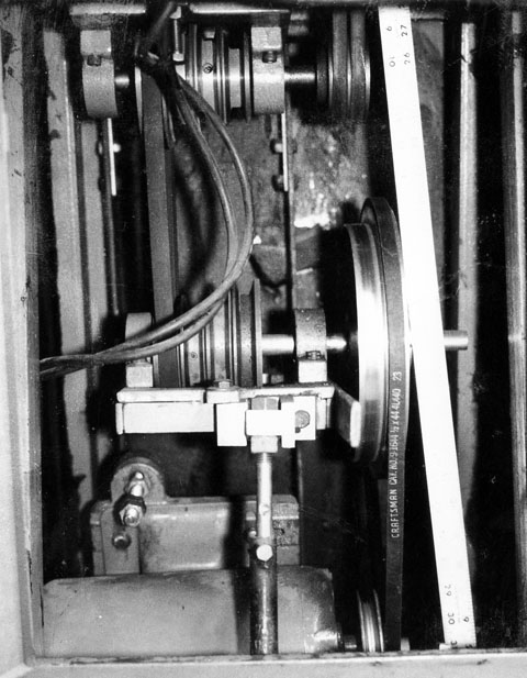
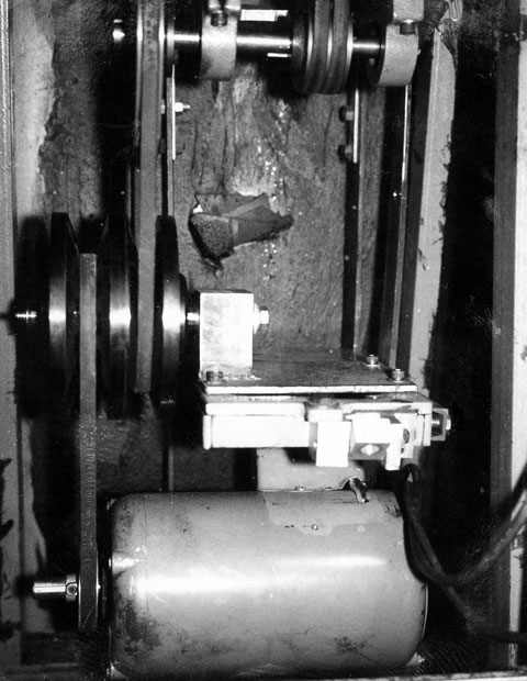
The
photo on the left is the lathe drive as it was when I inherited the
lathe; the one on the right is after I converted it to a split pulley
variable speed driveSome time after I completed these modifications, I found several old photos of the lathe drive as it was when I received it and of how it looked after I completed the variable speed drive modifications.. I am including them here merely for historical purposes:
The original cabinet lacked much in "curb appeal". Repainting the cabinet interior and the contents will help a lot. On the right you
see the mounting frame installed after moving it several inches to the left. This will allow the various components to fit and align with
the spindle belts which are really the only hard and fast location. The ugly splotch in the center of the wall is a stack of rubber pieces
my dad glued to jam between the sheet metal back wall and the frame (it used to be 1 inch further left) to dampen vibrations. I added
a couple pieces to do the same, but later found it was no longer necessary.
It is obvious to me that this mounting frame and the two upper shelves are not original Logan parts. Someone, probably my dad, modified
the factory configuration. I cannot figure out the original Logan setup, as any pictures I have found on the web show parts mounted on the
vertical frame members. There are no mounting holes in my frame.
I mounted the motor and temporarily installed the two best of the original pillow
blocks along with the pulleys as a temporary setup. I had to slot the mounting
holes of the motor slightly to align with the cast mounting slots in the bottom shelf.
I cannot believe how quietly my lathe runs now! There is none of the low frequency
rumble that used to echo in the sheet metal whenever the old motor was running.
As it is currently belted, I can run from about 50 RPM to about 900 RPM spindle
speed in direct drive with the allowable frequency range of the VFD programmed from
5 Hz to 90Hz. Back gear speeds are 1/6 of these. The addition of the step pulleys will
allow me to adjust these speeds up or down.
2/20/14
My pillow blocks just arrived. Did you know you can buy pillow block bearings from Amazon? It only took a couple of hours to get my two countershafts all set up. I had one new belt that worked for the cone pulley stage and a temporary 20 to 50 year old belt for the motor. It works, but will be replaced soon.
Here is my fully assembled drive system. It includes 4 new pillow block bearings and
new shafting. The cone pulleys have been out of commission for over 40 years, but
are still in excellent shape. All 3 belt tensioning rods have been added, completing
the mechanical part of this project.
While I was waiting for my pillow blocks to be delivered I wired up the VFD and a fused disconnect box. I plan to get an enclosure for the VFD as there is little protection the way it is designed. They are all supposed to be installed in larger boxes, but many people don't do that, and just mount the VFD by itself. While I was at it, I wired my existing drum switch to control the motor in the same manner as when it was connected to my previous motor. Now instead of controlling full motor voltage and current, it only controls a logic level of a few milliamps or less. In looking for a shielded multi-conductor cable (I only need 3 wires for this function) I found a 10 foot Centronics type printer cable in my garage. I have not had a printer using a Centronics connector for at least a decade, so I lopped off one connector, and sure enough, the cable was shielded. As I said I only need 3 conductors - this had about 25! They were small at around 24 ga. I also kept several other wires as spares and cut off the rest. I also had a serial cable that was shielded with a lot fewer conductors, but it was less than 3/16 inch diameter so I was afraid of it getting snagged or damaged. The cable I used is about 3/8 diameter, and will not easily get pinched between parts.
I installed the VFD and the disconnect box on a board, leaving room for the enclosure I will be adding.
I figured this was a good way to mount the items as well as allowing me to wire most of it at my bench.
The duplex outlet is switched on and off with the main lathe power, and will be used for my tach and
possibly for an AC power supply for my DRO's. This picture shows the spindle running at 265 RPM
at a frequency of 35.0 Hz.
I decided to temporarily wire up my existing drum switch to control the on/off/reverse functions as that is what I
instinctively reach for, and I have it now. I will probably change it to start and stop buttons and a reverse switch shortly, it
is a simple matter. At this time, I am using the pot on the drive unit to control my speed. I have a
10k linear Allen Bradley pot just waiting for me to mount and wire in, but at this time, the VFD is as
handy as any place I have to mount it.
So far, I am very pleased with the ease of control, the speed range I can set, and especially the quiet running.
Change of Plans 2/26/14
I ended up ordering a somewhat larger enclosure than I had originally planned. The VFD manual indicated I needed more space around the unit for proper cooling. After seeing the size of my new enclosure I decided it was foolish to have all the extra ugly gear for disconnect and extra outlet showing, I could incorporate all that into the enclosure itself. I ordered a two pushbutton machinery type on/off switch and found a surplus porcelain cartridge fuse holder and the class fuse the VFD manufacturer recommended. I decided to mount the VFD so the front panel protrudes slightly through the front cover of the box. This still gives me access to the buttons and knob for setup and control, and lets me see the output frequency, while protecting it from debris and accidental electrical contact.
I cut the holes for the VFD and the on/off switch using my mill. The large box is very
awkward to handle and setup. When I cut the large hole I had to cut half from one
side, then turn the box around to cut the other. I guess I need a larger mill! Or I
could have extended the head of the mill out further, but then I would be faced
with a lengthy alignment process to put it back accurately.
I have mounted the assembled box. It looks so much better than my previous
kludge! The on/off switch just came in and I was able to finish this project.
Relook at the mechanics (3/6/14)
I have noticed that it is very hard to adjust the belt from the motor to the lower step pulley shaft, and that I had to get an exact length belt for it to work. Looking at the geometry of the motor, its pivot point and the location of the pulleys I saw that the motor pulley moved almost at right angles to the shaft center lines, meaning that moving the motor a lot, tightened or loosened the belt very little. This is a fatal situation to my plans of an eccentric lever loosening the step pulley belt enough to change ratios, as the motor belt would not let the motor lift.
I decided to totally remount the motor, hanging it from the middle shelf and relocating the pivot to be level with the motor shaft for maximum adjustability of the belt. Also, when I swing the middle shelf to loosen the step belt, the motor just moves with it with no relative motion between the two.
On the left you can see that the pivot point is almost in line with the pulleys, so that there is very little change in the belt tension for a large movement of the motor. In
fact, if the motor is lifted more than a few degrees, the belt starts tightening again.
On the right, the pivot point has been moved even with the motor centerline and now a small movement of the motor will have a large effect on the belt tightness.
Also, when I move the middle shelf (top in this diagram) to adjust the step pulley belt, the motor will now swing with it, with no effect on its belt tension.
On the left you can see the center shelf with the added brackets hanging down to provide a pivot for the motor.
On the right is the motor shelf with two brackets going up to complete the pivoting mount.
I tried really hard to get a good picture of the final assembly. It just cannot be seen
from outside the cabinet. I finally got this shot by holding the camera at arm's length
inside the cabinet and shooting blind (one of several I tried). It at least shows one side
of the combined brackets and the new raised pivot point.
Control changes
As I stated above, I decided to keep the drum switch as my main control for the time being. It works well, but I really want to do it right. I have ordered start and stop pushbuttons and a reversing switch. The VFD will readily accommodate these. I bought a plastic outdoor double outlet box which should have enough room to mount these new controls along with a speed controlling potentiometer. The box should fit OK on the front of the headstock where the current drum switch is mounted.
March 19, 2014
Buttons and switches
I milled out all the excess studs and the inner part of the conduit inlet from the outlet box, mounted the buttons, switch, and potentiometer. I made a hard-wood mount on the front of the lathe, attached the control box, and wired it all up. A couple of changed function codes on the VFD, and it all worked correctly.
I made a mount from oak which attaches using the same holes which held the
drum switch.
The finished control box is mounted and wired. You set the direction of the spindle
using the Forward/Reverse switch on the upper left. You then press the green
start switch and it runs. You control the speed using the knob on the lower left.
To stop, you press the red stop button.
Yet
more changes 3/27/2014
Now that I have had a chance to use the new controls for a little while I have found some things I don't like. The box hangs out farther than I am comfortable with. There is no real danger as the only button which might be accidentally bumped is the stop button. There is a small chance of bumping the speed dial and changing it, but not likely. The biggest physical problem I have encountered so far is that if I try to use my 3 jaw chuck wrench on the front of the chuck, the handle hits the box and cannot be turned. This is a small annoyance, but it bugs me.
I have been planning all along to replace the temporary bar which has my DRO readout heads and my tachometer on it with an enclosed box. It just so happens that I have an unused 8" x 8" x 4" plastic junction box I bought when I was converting my electric truck, but didn't use. I have decided to use it to mount the DROs, the tachometer, and the control switches in it. I will then mount a much smaller box on the front of the headstock with my emergency stop button.
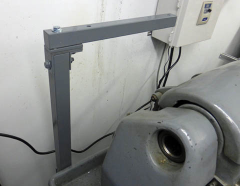
I evaluated several methods to mount the control box and decided a post with a
horizontal arm would give me good adjustability and a strong mount.
I made a layout
of the front panel of the
control box and machined the cutouts as well as pressing a mounting
bolt into the box. It mounts nicely on the mounting arm and I
think it will do well.
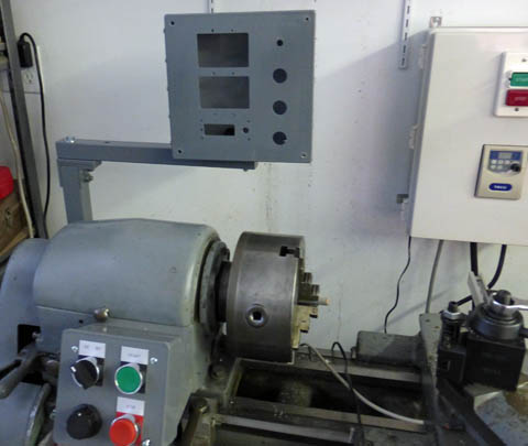
The box is temporarily mounted in place. The front panel cutouts include the DROs
in the upper left, the MachTach bottom left, and the control switches on the right.
The DROs either mount on a supplied plastic clip, or by magnets in the back of the
case. The clip is too loose to properly hold it in position. The magnets hold well
but on my temporary bar, slide around too easily. To mount them in this box, I
made a steel plate to magnetically attach to, while the panel cutouts will constrain
them in the correct position. The angle on the steel piece is there only because that
was a convenient piece of steel I had.
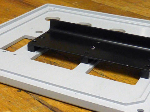
I took my
original "full size" MachTach
tachometer and cut the board in two to make the "half size"
unit.
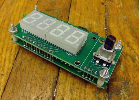
It is designed to be used with the circuit board intact or to have
the board split in two and stacked to fit in a smaller panel
size. After splitting, there are 16 jumpers that need to be
added
between the boards. I then completed mounting it and the
other
components in my control box.
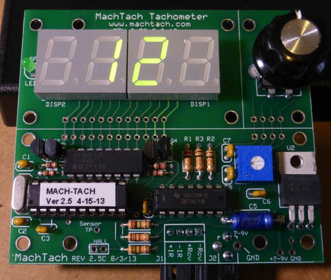
On the left is my original "full size" tachometer. I used my bandsaw to cut it into two pieces along the horizontal white line in the center.
I then mounted the two pieces on spacers and added 16 jumpers between the two halves and voila - a much smaller unit!
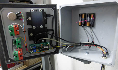
All the components are now mounted and the final wiring is connected. The AA batteries
are connected onto the DRO cables and replace the small internal button batteries. These
batteries should last a very long time and when they do need replacement will not require
un-mounting the DROs.
The wiring is complete and it all functions correctly!
Update of 5/7/15
It has now been over a year since I installed the DRO's with the external AA batteries. During that time I have left the DRO's turned on continuously. They are still going strong with no indication of the batteries weakening. With the original button cell batteries, I was only turning on the units when I needed them and the batteries died in about a month. These batteries are inexpensive and last so much longer!
On the left is my original "full size" tachometer. I used my bandsaw to cut it into two pieces along the horizontal white line in the center.
I then mounted the two pieces on spacers and added 16 jumpers between the two halves and voila - a much smaller unit!
All the components are now mounted and the final wiring is connected. The AA batteries
are connected onto the DRO cables and replace the small internal button batteries. These
batteries should last a very long time and when they do need replacement will not require
un-mounting the DROs.
The wiring is complete and it all functions correctly!
Update of 5/7/15
It has now been over a year since I installed the DRO's with the external AA batteries. During that time I have left the DRO's turned on continuously. They are still going strong with no indication of the batteries weakening. With the original button cell batteries, I was only turning on the units when I needed them and the batteries died in about a month. These batteries are inexpensive and last so much longer!
Richard Mason
3/3/2014