Home Trips Motor Home
Projects
3D Print, House,
& Misc. Projects
 Machine Shop
Projects
Automotive
Projects
Early Computer
Days
About


Adding Low Cost DROs to my Lathe

Note of 4/9/2021:

The following describes adding digital readouts to my lathe in 3 distinct steps:  First I added low cost capacitive scales with their native readouts.  About 7 years later, I updated these "reasonable accuracy" scales with an easy to read large scale display.  The third step shortly later was to replace both the scales and the display with a very low cost commercial DRO using much better accuracy glass scales and a dedicated readout assembly.

December 2013

There is a newer entry into the DRO mix.  These are capacitive pickups similar to the technology used on digital calipers.  They are very inexpensive and have a reasonable accuracy of about .001 to .002 per foot of scale length.  Due to their very low cost and acceptable accuracy, these are finding a wide acceptance in the hobby and home machine shop markets.  I decided to use this series of scales on my lathe, as I blew my budget on the mill system.  I bought several of these DRO scales at a cost ranging from about $21 for the 6 inch ones to about $35 for the 36 inch unit.  These units have a small digital readout at the end of a several foot wire.  I plan to mount the displays on a post behind the headstock of the lathe.


This is a small DRO from iGaging Co. which has a printed circuit pattern under the black
stripe.  The sensor is able to capacitively read the locations within this pattern and convert
them to a length measurement.  As you can see it has a relatively small readout panel and the
readout resolution is .0005 inches with an absolute accuracy  of about .002 per foot.  It is
about 1/10 the cost of a standard DRO.

I plan to mount a scale with 36 inch travel on the rear of my lathe to measure the carriage movement, and a second short one on the cross feed to measure my depth of cut.  I doubt I will be able to fit a third unit on my compound rest, as it is just too small.

Progress:

It took very little time to mount my 36 inch scale on the rear of my lathe.  There is plenty of room and to test it out, I used two very powerful Neodymium magnets, removed from obsolete computer hard drives.  Mounting consisted of placing a magnet on each mounting bracket and placing it on the lathe.  It holds very well.  I then made a formed sheet aluminum bracket which attaches to an existing bolt on the carriage and I had a working DRO for the Z axis.  I know!  Z axis sounds wrong, but technically the Z axis is defined as the axis parallel to the spindle on a machine tool, therefore the carriage moves in the Z axis.

In operation it works great.  It displays the position to the nearest 1/2 thousandth.  You can use a relative mode and zero the scale anywhere you like without disturbing the primary readings.  It displays inches, millimeters, or inches and fractions.  The latter seems totally useless to me, as it reads in 64's of an inch which is about 30 times its minimum resolution (and who can look at fractions in 64's and instantly comprehend the magnitude?).  The biggest problem I see with these scales is that they use small enclosed batteries which risk early discharge if you forget to turn them off when you are finished.  I plan to look into an AC powered supply for them after getting further into the project.


The first scale I mounted was the lathe Z axis.  This is a 36 inch scale.  I have
initially mounted it to the lathe with 2 strong magnets.  The read head is attached to the carriage
with a small aluminum bracket.  Now that I have proven it out, I will replace the magnets with
tapped holes and screws.  In this picture the readout is still plastic wrapped and is laying in
 the foreground.


I also temporarily mounted a much shorter scale on the cross slide, but there are problems there.  As presently configured there is really only one place to mount the scale.  That is on the spindle (left) side of the cross feed, with the slider between the ways.  In this position, it is quite possible to run the read head into the chuck if you are working close to that end (fortunately, I never did!).  There is not adequate material at the rear of the cross slide to mount the scale, and in this position, it accumulates a major portion of the machining swarf.  This is particularly obvious when I machine steel, as each end, where the magnets hold the scale, builds up a large ball of chips.


The temporary cross slide scale is also mounted using magnets.  This mounting is not
satisfactory as the read head will hit the chuck if the carriage is moved too far.  Also it is
mounted  in the area where the most chips fall, many of them hot enough to melt plastic.

This mounting method was just not satisfactory, so I made some changes to the cross slide and mounted the DRO on the right side of the carriage.

Final DRO Mounting March 26, 2014

To mount the scale on the right side of the cross slide, I had to machine a true mounting surface.  I then mounted a strip of aluminum as a backing plate for the DRO.


I used a length of drill rod clamped in the dovetail to align the cross slide.  I then
took a surface cut of about .050 where the aluminum is to mount, to make a
uniform mounting surface.


I have mounted the backing plate.  As the plate covers one of the gib adjusting
screws, I provided a clearance hole.  Also after taking this picture, I beveled
the end of the plate to allow allen wrench access to the compound clamping screw.


The left picture shows the aluminum backing plate mounted to the cross slide.

The right picture shows the scale mounted to the plate.  I verified that it is parallel to the travel within .002.  The read head is attached to the carriage
using a thin aluminum bracket, machined to allow flexibility in the two minor axes, and good stiffness along the axis.

I then went back and removed the magnets from the Z axis scale, drilled and tapped the mounting holes and mounted and aligned the scale.


The longitudinal axis DRO scale is now mounted with screws instead of the magnets.
I never had a bit of trouble with the magnetic mounting, but this is secure.  You can
also see the narrow flexible bracket driving the X axis DRO in the upper left of
the picture.  The finger will readily flex sideways and vertically, but is very stiff
in and out, driving the read head.


I mounted the DRO heads and my tachometer on a temporary mounting bar.


As part of the "Replacing my lathe motor" section, I mounted the DRO heads in a multifunction control box instead of the bar of metal I was temporarily using.  This is much more satisfactory!


The DRO heads are mounted in a control box along with the MachTach and the
VFD and lathe motor controls.


Addendum of February 2021:

These low cost DROs have been working fairly well for the last 7+ years , but there have been problems.  Occasionally, a readout would change by some radical amount and be totally useless, until I reset the zero.  I also don't use them as often as I should.  I guess the tiny, unlit numbers and the yet smaller buttons just make it awkward enough that I ignore them for many minor jobs.

About the time I originally installed these DROs, I was investigating the work a serious hobbyist was doing to make a large scale readout for these units.  His name is Yuriy Krusheinytskiy, but everyone just calls him Yuriy.  At that time he had designed an Arduino based interface which communicated with a tablet or phone using Bluetooth.  I built a test circuit following his instructions, consisting of an Arduino controller, a Bluetooth adapter and a shield for the Arduino with a lot of interconnecting wires.  I successfully tried it on a single channel, but the construction and the operation were not what I wanted to undertake at the time.  Also, I did not have a suitable tablet for the project. 

I recently re-visited his site and WOW!, has he advanced!  He now offers a collection of complete boards, and a couple of do-it-yourself boards to act as an interface between the capacitive scales and a tablet.  He also has models that support magnetic and glass scales. Each of these variations is contained on one of a series of small circuit boards, ready to plug in your scales and a power supply.  He has named his products TouchDRO.  I decided to try one out and bought an I-gaging compatible board.


This tiny board contains everything needed to monitor up to 4 axes and, using Bluetooth, send the output to the TouchDRO
 app on an Android tablet.  The green board is the Bluetooth module, and just to its right is the microprocessor.  The case
 is Yuriy's design and I printed it from his files.


I initially hooked the board and a spare scale together on the bench to try it.  It worked quite well, but I did notice that it was quite sensitive to interference, especially on the power supply.  Some 5 volt wall adapters worked fine, while others caused the readings to jump around and change numbers rapidly.  Yuriy warned that certain steps must be taken for smooth reliability.  He warned about the different power supplies, but concentrated on the grounding of the system.  His suggestions were:
 
  1.  Insulate the scales from the machine.
  2.  Replace the unshielded original wires from the scales with shielded ones, but connect the shield to ground only at the controller end.
  3.  Ground the controller to the machine frame.
  4.  Use an old style transformer based power supply, not a switching one, for the 5 volt input.

According to him, this would insure that you had no ground loops, and that you would have no power line interference.
(Remember way back, when you connected an extra cable in your hi-fi and got a loud hum?  That was a ground loop!)

I followed his advice very closely.  I insulated the scales from the body of the lathe.  I cut the cable close to the sliding reader and spliced it to a shielded micro-USB cable that would plug into the adapter board.  And I grounded the controller to the frame of the lathe.


To insulate the carriage scale, I 3D printed mounting brackets that mimicked the function of the pressed steel original brackets.  The mount to the sliding reader is fastened to
inserts in the plastic cover, and were therefore already insulated.  For the cross slide, I simply replaced the metal spacers with printed plastic ones and used nylon screws.

My power supplies were getting out of control!  I already had a large 12 volt supply for the lathe light, and a smaller 7 volt one for the tachometer.  I now needed to add a "quiet" supply for the adapter board and a 5 volt supply for the tablet.  Instead, I used two buck converters, which are a very efficient way to reduce voltage.  I printed a small case to mount two of these and connected them to the light's 12 volt supply.  I adjusted one of the buck converters to supply 7.5 volts and fed it to the tachometer, and set the other to 5 volts to feed the DRO adapter.  I had already verified that neither the tach nor the light had any connection to the lathe ground, so no ground loops here.  I wasn't sure the buck converter power would be clean enough for the DROs, but it turned out fine.  Now I have just one power supply, which turns on and off with the lathe power, powering the light, the tach, and the DRO adapter.  I want the tablet supply to be on all the time so the tablet does not discharge its battery all the way, so therefore it will be plugged into a normal wall outlet.


The left picture shows the case I printed and the two buck converters.  The middle shows them installed and wired, while the right shows the DRO adapter (upper-left) and the buck converters
(center-right) mounted inside the case.  The door of the case shows where the original DRO displays were mounted.


When I initially experimented with Yuriy's DRO about 7 years ago, the only tablet I had was a color Nook.  I was never able to make a satisfactory connection from this to the DROs and that was a large factor in my not continuing the project.  Since that time I have bought a Samsung tablet and have been given two other cheap, no-name tablets. 

As part of my current experiments, I tried all three of these tablets.  For some reason, my Samsung was not able to stay connected to the DROs.  It would connect just fine, operate just fine, then without warning it would disconnect.  I finally worked through a password problem on one of the other tablets, only to find that there was no support for Bluetooth!  The third tablet was the charm!  I was able to get it working, load Yuriy's app, and connect it to the DROs.

Now I need to mount the tablet somewhere.  The logical choice is the face of the control box, covering up the openings where the old displays were.  To do this I designed a 3D printed frame into which I could slide the tablet, with a small clip at the end to latch it in place.


The tablet holder is designed to fasten to the 4 existing holes in the control box cover, plus one more for added stability.  A small clip at the upper left has a tab which drops down to
lock the tablet in place.  The right picture shows this mounted along with a thin printed sheet to cover the openings in the cover left by the original display modules.


This is the completed installation.  These numbers are very easy to see.  The setup of the display is very flexible, and can be adjusted
significantly from within the app.


Conclusions:

So far this looks like an economical, but significant improvement in the operation of the DROs already installed on the lathe.  Time will tell whether I still experience the occasional jump in the readings.  While the display has been greatly improved, there is no improvement in the accuracy of these low cost scales.  Their accuracy is listed as +-0.002 per foot of length.  As my Z axis is a 3 foot scale, I could experience errors of as much as +-0.006. 

I realized part way through this upgrade that this was probably not the optimum answer for me.  While it makes the readings much more visible and would certainly induce me to use it more frequently than I have been, it is still a nuisance to start up, and offers no improvement in accuracy.  To start it, in addition to starting the lathe normally, you must also turn on the tablet, and swipe the screen to activate it.  Sometimes it comes right up with the readings and you are ready to go.  Other times you must click a couple places to start the bluetooth connection.  Often, after several seconds, for some reason it drops the connection and you must start over.  After that, it usually works just fine.  Also, when you shut down, you must remember to turn off the tablet.  Being primarily a battery operated device, there is no way to just plug it into the lathe control box and power it on and off automatically.

In looking at several sources for complete DRO packages, I found several available for about $170 that include a DRO display and two glass scales and mounting hardware.  Reviews of these cheap system showed that they work quite well, are reliable, and have an accuracy about an order of magnitude better than the capacitive scale systems.

I decided that in spite of this experiment being a success, that I would upgrade to a full system.

Upgrade of April 2021:  (Yet another Covid project!)

Looking through the DRO offerings on Amazon, Ebay, Banggood, etc. I found a number of truly low cost units available.  Many offered each part individually priced, and you selected the exact parts you need to build your kit.  Others offered a variety of display and pre-selected glass scale combinations that seemed less expensive than buying individual pieces.  I found one offering that provided the exact combination of scales and display I needed for my lathe, and ordered it.  the cost was about $170, but I spent $16 extra to upgrade the scale for the cross axis from a 5 micron to a 1 micron resolution scale.  There are two reasons a higher resolution is beneficial on this axis: 

1.  Usually a higher precision is required for the diameters of parts than for the lengths, and, 
2.  The cross slide scale value is doubled to show the diameter while the scale reads the radius, thus doubling the effective minimum resolution.

Note: one micron is 1 millionth of a meter, which is 40 millionths of an inch, or in machinist's lingo, 0.4 of a tenth (of a thousandth).  In contrast, a 5 micron scale has a resolution of about 2 tenths of a thousandth.

The quality and appearance of the components look surprisingly good, and during a pre-installation test, everything seemed to work correctly.  I was even surprised by the manual.  All online references to the Chinese DRO manuals seem to be really critical.  They say that the "Chinglish" used is hard to understand, and that they really don't cover the topics well.  This manual is quite understandable and seems to cover the functions quite well.  Where it lacks is any installation information at all.  There is a page explaining the initial configuration options, but unfortunately, there are two independent setup menus, accessed by very different methods, and the manual only tells about one.  Both are needed to configure the DRO.  Thank you Youtube!


The kit I bought looks something like this. (the long scale is actually much longer)   It includes the main display,scales with travel lengths of 200mm (8 in.) and
1950mm (38 in.) along with mounting brackets, hardware, and scale covers.  The included manual does a fair job of describing the operation of an installed
system, but makes no mention of any installation requirements or tolerances.

Z axis:

I started by installing the long Z axis scale.  In principle it is mounted similarly to the way the old scale was mounted, but requires far better alignment.  To achieve this degree of accuracy it is mounted on a pair of blocks fastened to the rough casting of the lathe using a couple retaining screws and several grub screws.  The grub screws are adjusted to align the block as needed for proper distance and angle from the casting.  The final scale alignment is verified using a dial indicator on the top and outside surfaces to assure that each is parallel with the movement of the carriage.

  
The left shows one of the adjustable mounting blocks.  The right shows checking for alignment parallel to the carriage movement.  The mounting
blocks have already been set to vertical and to be in alignment with each other.


This shows the bracketry driving the scale trolley as the carriage moves.  There is an adjustable plate mounted to the lathe using grub
screws to align it to vertical.  A vertical bracket mounts to this and is adjustable up and down.  To that, a small plate connects to the mounting
screws of the read head (called trolley).  The scale body is stationary and the trolley moves with the carriage.


X axis:

The cross slide or X axis is installed in an unconventional manner.  Most installations mount the scale on the side of the slide.  This is the way the capacitive slide was mounted.  With that mounting, the thickness of the slide increases the minimum distance between the tailstock and the carriage, and I do not like that!  For this installation, I decided to hang the slide off the rear of the lathe, keeping the path of the tailstock clear.  I can now bring the tailstock to within 1/16 inch of where I could before the installation.  I also reversed the mounting, holding the scale fixed and moving the trolley.  The capacitive scale moved with the cross slide and the trolley was fixed.

To hang the scale off the rear, I needed a stable mount.  I decided to mount a 1/2 inch thick aluminum block to the carriage casting, using grub screws for adjustment, and have another piece of 1/2 inch stock bolted securely to the top, extending back.  On top of this piece I fastened an extruded aluminum 0.9 x 0.9 by 1/4 thick angle.  This is an ideal size to mount the scale.  The final assembly is very strong and stable, and has been adjusted to be accurately aligned.


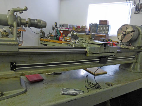
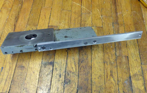
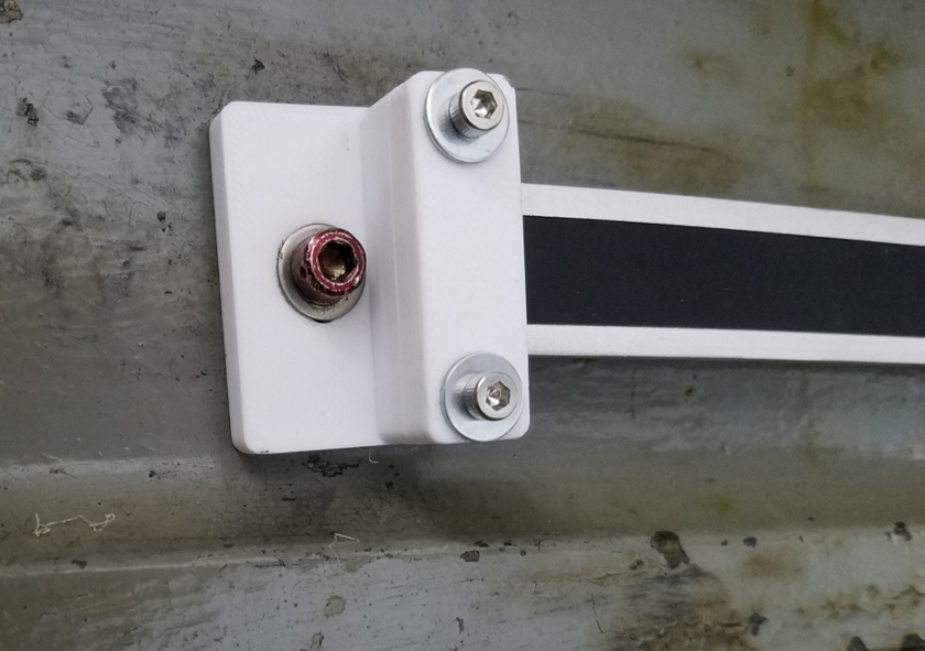
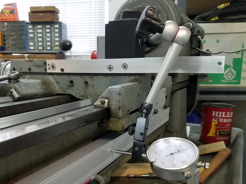
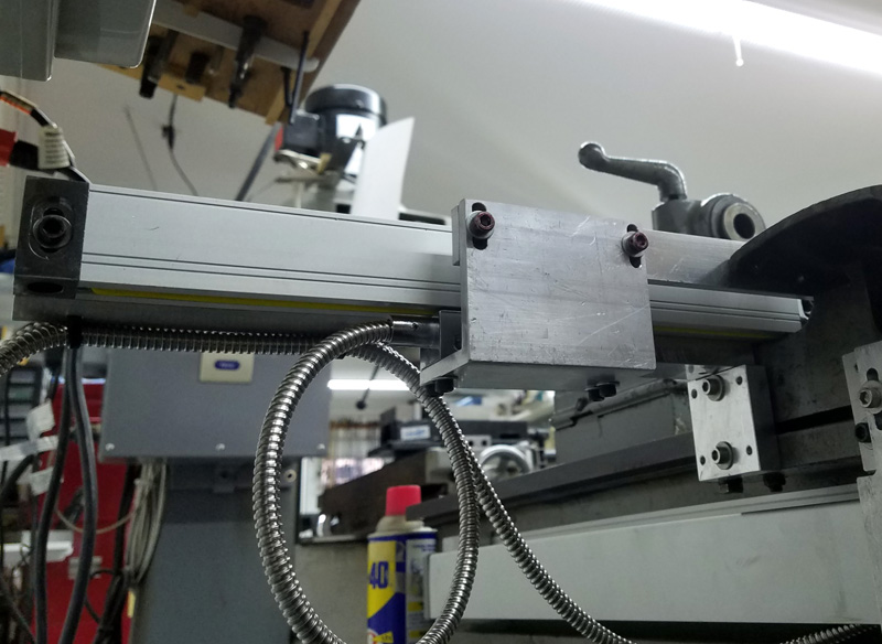
The left shows the X axis from the tailstock end of the lathe.  You can see the adjustable mounting block, and the somewhat narrower support bar attached at right angles.  To this bar is
fastened the 1/4 inch thick angle with the leg facing us.

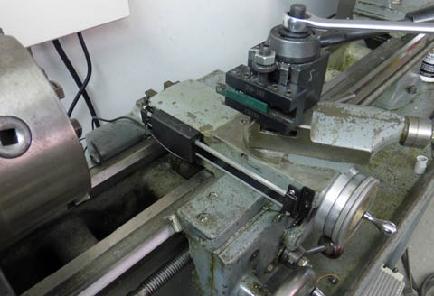
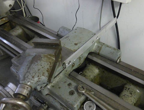
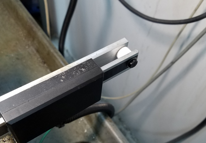
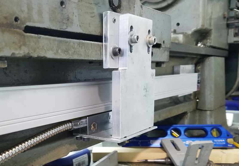
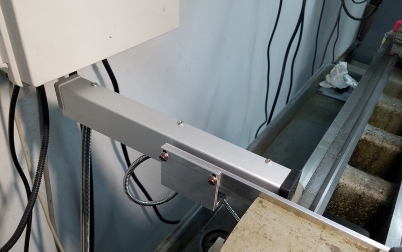
The right shows it from the headstock end.  We can see the scale attached to the flat side of the angle and the trolley driving brackets.  I used the mounting rail which previously supported the
capacitive scale intact except for adding one threaded hole and it is now used to drive the trolley.


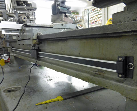
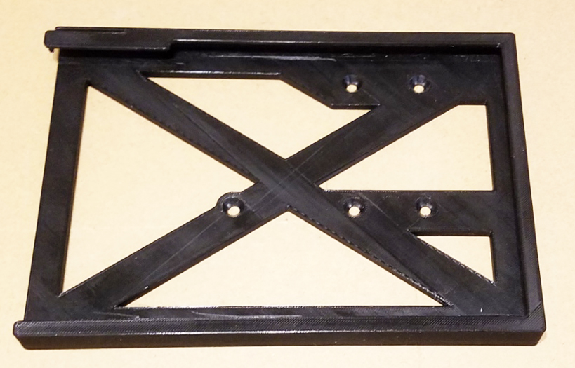
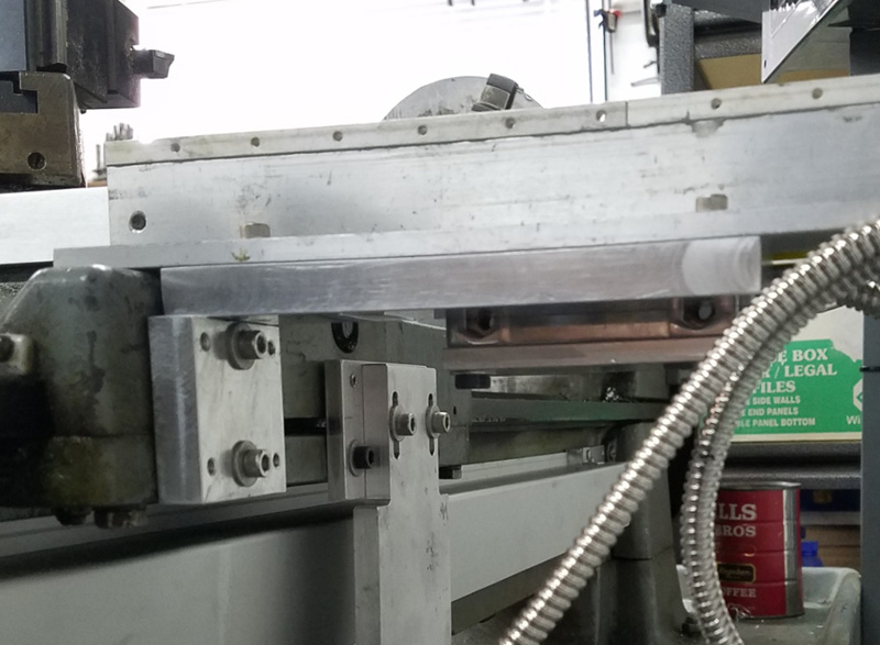
I left the design of mounting the X scale cover until after mounting everything else, to see just what I needed to work around etc.  When fitting the cover I found I needed to raise it
3/16 to 1/4 inch and provide tapped mounting holes to attach the cover.  I had some 1/4 square aluminum bars with many tapped 4-40 holes.  I drilled out 3 and tapped them to
8-32, then used JB Weld epoxy to attach the bars to the top of the angle.  This gave me both the space and the mounting holes.  To make sure the epoxy bond on the thin 1/4 inch wide angle
would withstand a force or a blow to the top (heaven forbid!), I attached several stick-on soft plastic feet to the inside of the cover side, to bear on the scale if the cover is pressed down.


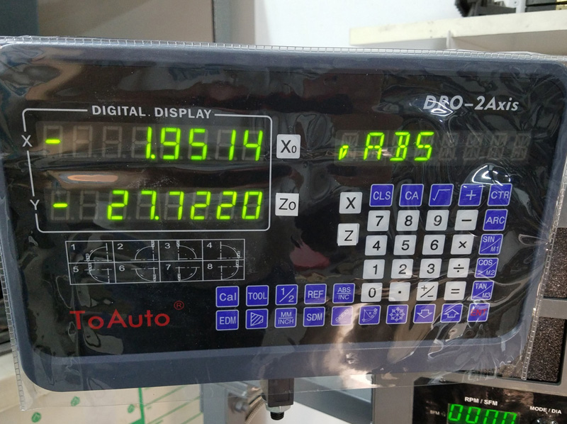
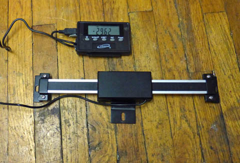
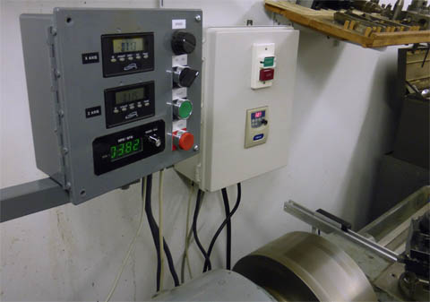
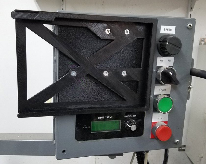
This is the DRO display.  There are many special functions which would be applicable to a mill, such as bolt circles,
lines of holes at any angle, and rounded surfaces, which make no sense for a lathe.  One feature which may be
very useful is a 200 entry tool library.  This would allow changing from one tool to another without having
to re-calibrate the readings on the DRO.  The differences in dimensions would be automatically adjusted
as you specify a different (pre calibrated) tool.

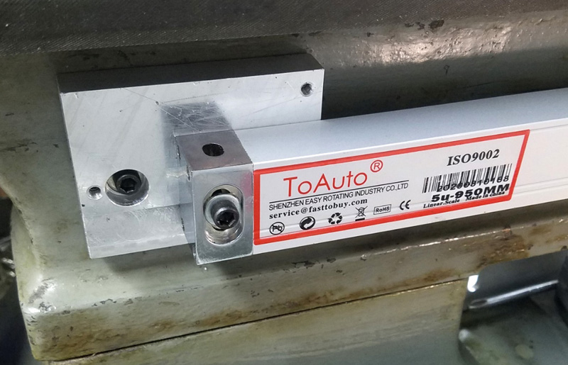
The small triangle before the "ABS" (absolute mode) indicates that the X cross slide axis is reading double the
actual movement.  Knowing the part's diameter is usually more useful than the radius.


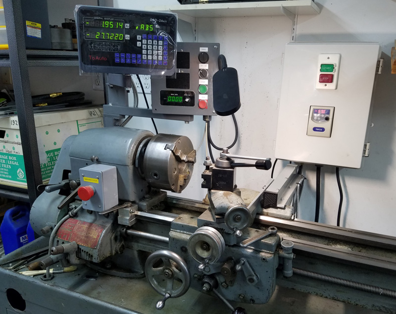
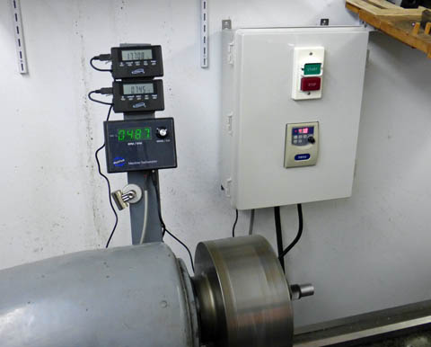
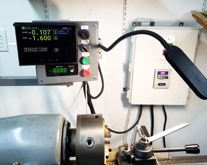
Here is the finished installation.  The DRO powers up whenever the power is turned on to the lathe.  The readings are remembered
from one cycle to the next, as long as the carriage and cross slide have not been moved while the power is off.  The display is mounted
using the included hardware.  I mounted it to a small piece of oak which is attached to the crossbar holding the control box.  I raised the
mounting of the lathe's power box on the wall to allow the extended X scale to pass under it.


Conclusion:

The installation went smoothly and everything appears to be working correctly.  I am encouraged that when I next use the lathe, the DRO will be easy to use and helpful.  It should help immensely when I need to make parts to a high level of accuracy!  More after I actually have a chance to use it.

One year later, April 2022:

The lathe is a joy to use with the new DRO!  I have a large, clearly visible pair of readings for both the cross slide position and the carriage position.  It is so easy to use now that I use it constantly without even thinking about it.  The results have been steady and reliable, and have allowed me to create parts with more accurate dimensions than I ever could before.


GO BACK TO "Machine Shop Projects"

Richard S. Mason  12/2013