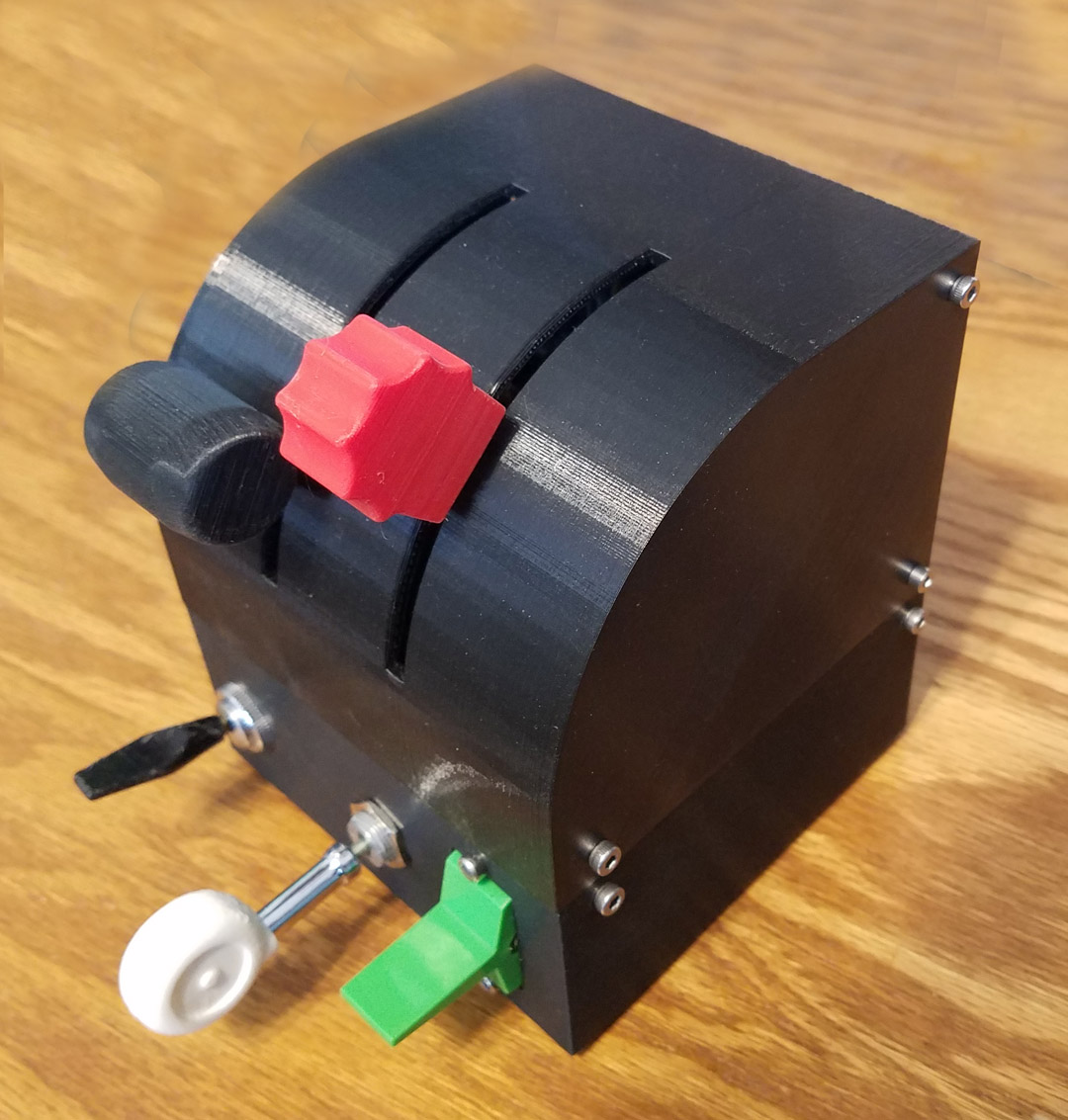
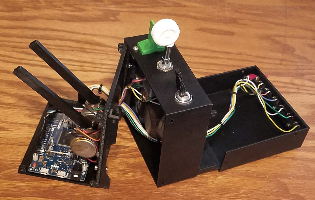
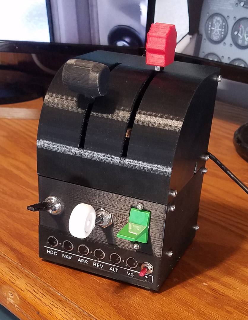
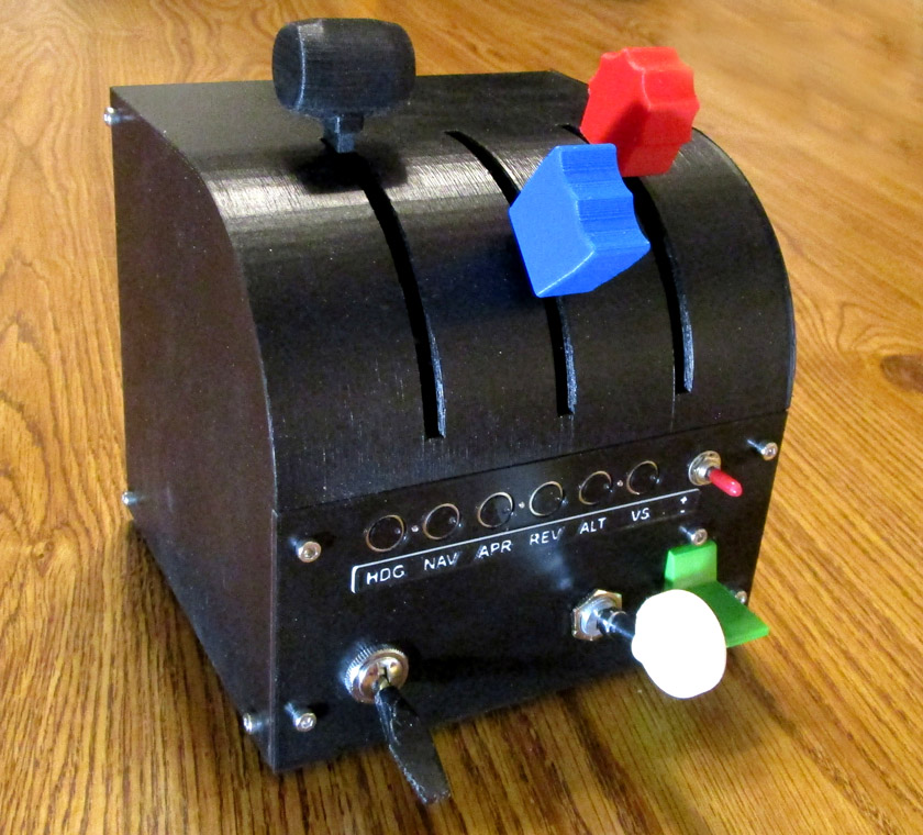
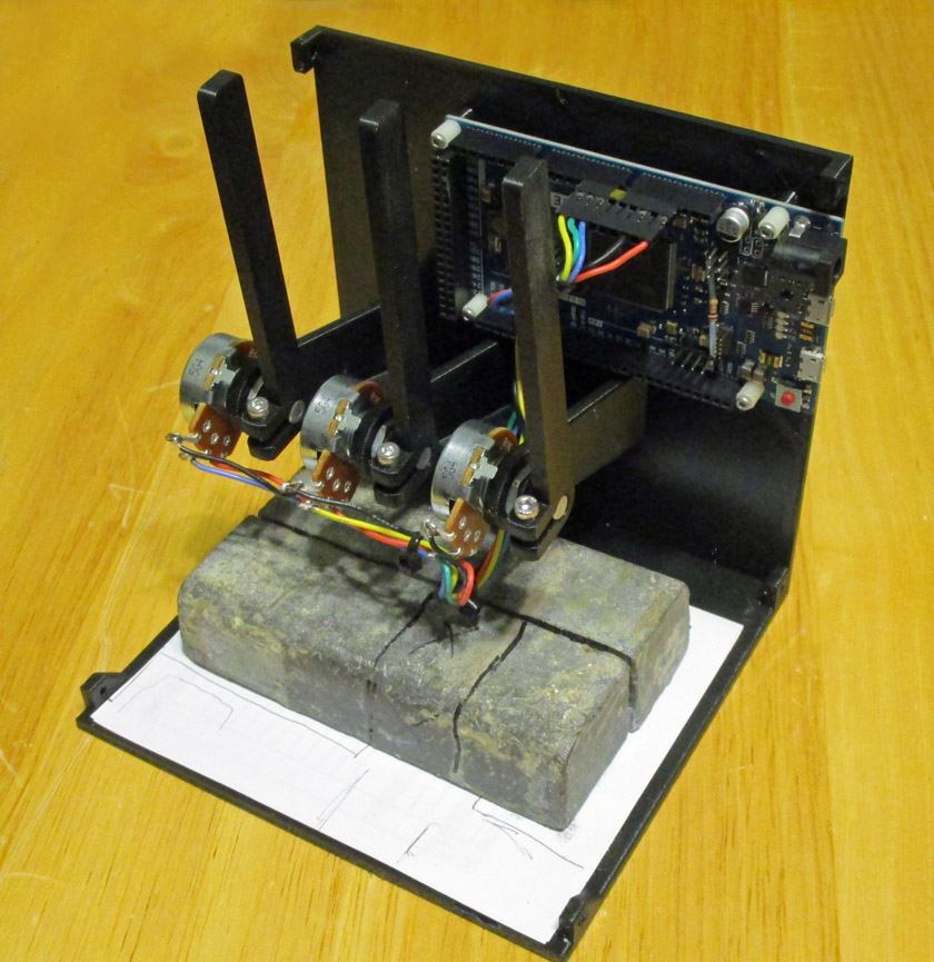
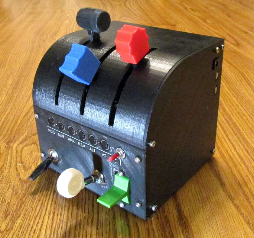
This is the re-designed unit. In addition to overall better
appearance, it adds the blue prop control, the autopilot controls
are above the switches where they are easier to use, all the switches and buttons are on an easily removable plate, and the
external connectors are now on the right hand side where the cable will be less in the way.
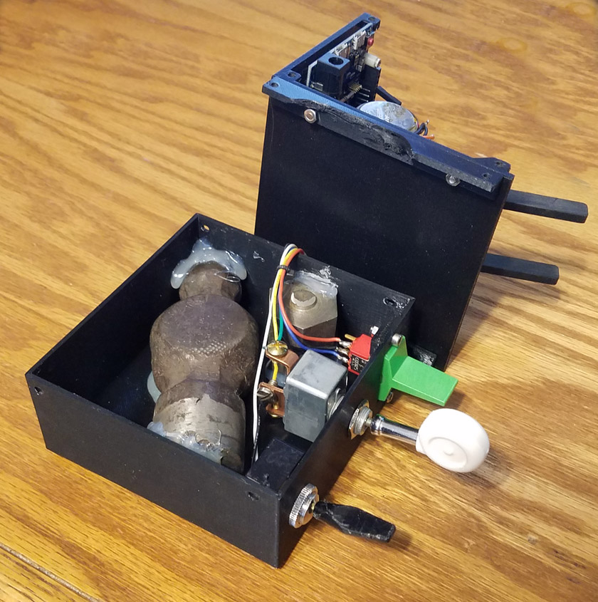
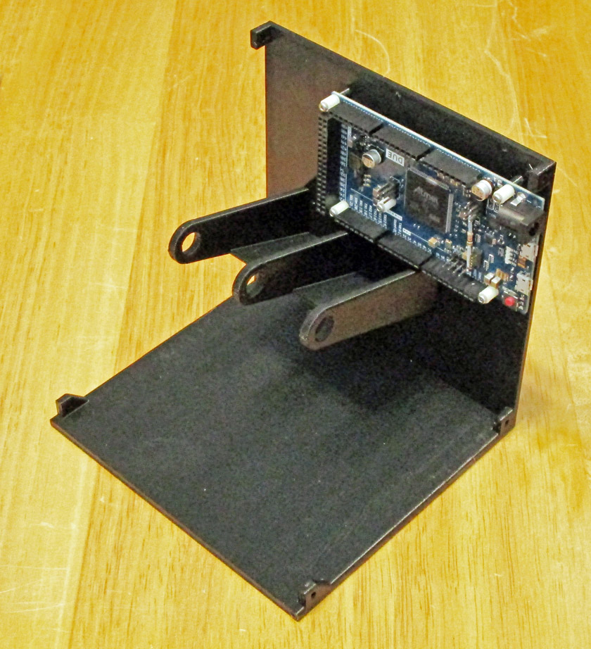
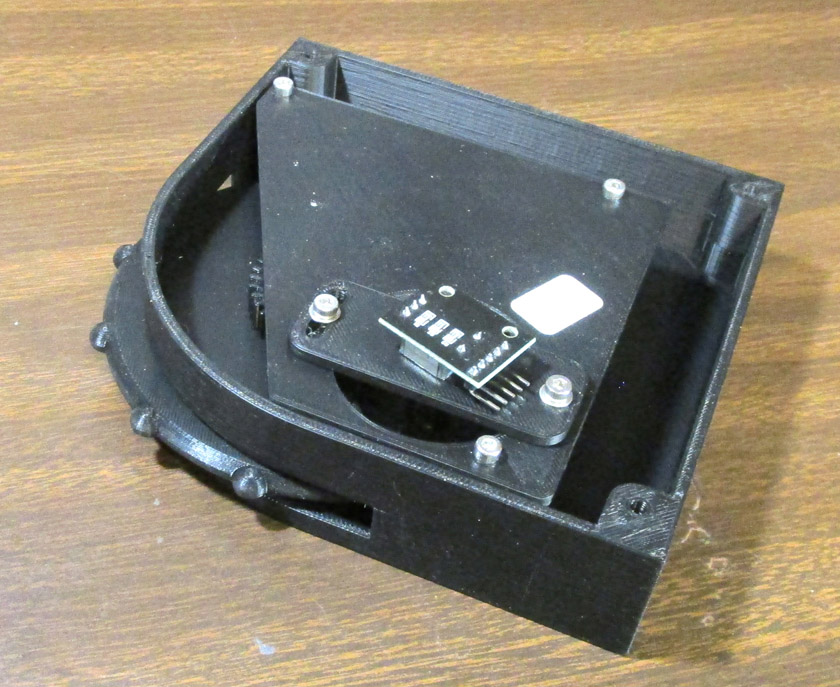
The left shows the main frame with the Arduino mounted. The
potentiometer mounts are now much longer since there is no shelf right
below them but there is more room in all directions.
The right shows the test fitting of 4 pounds of lead to replace the 2.5
pound hammer head and scrap steel. The lead will be screwed and
glued in place.
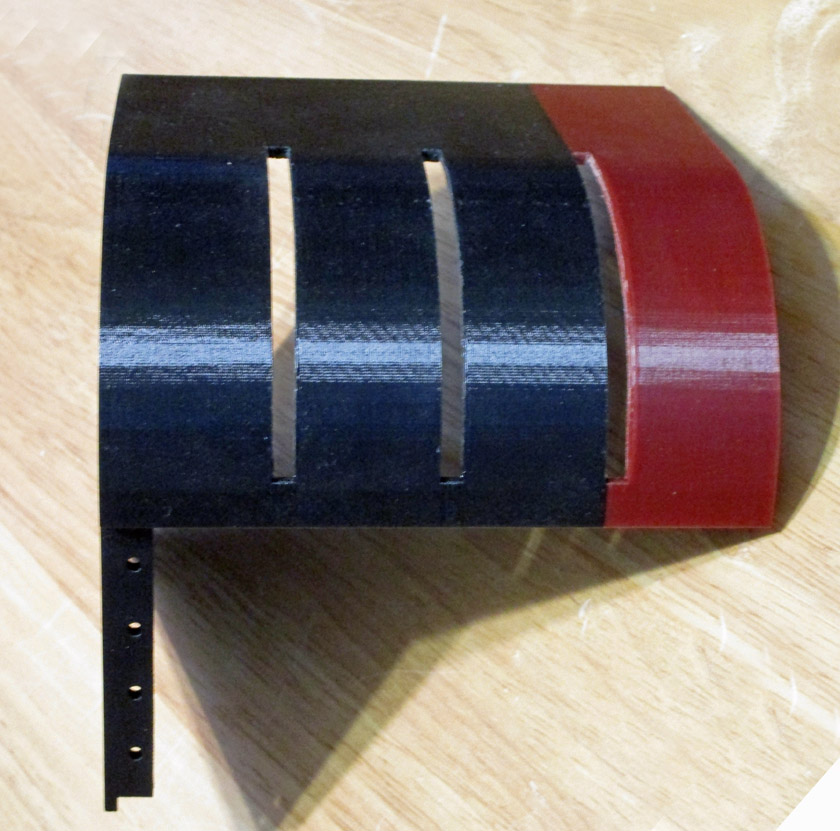
The cover was a 12 hour print, I was running low on black
filament, and my replacement spool was still 2 days away. I carefully
weighed what I had left by weighing the
filament spool and subtracting the weight of an empty spool. I had 165 grams, the slicer said I
needed 130. They were wrong!
Once I saw I would never make it, I saved a small amount of black for the outside
of the switch plate.
A quick couple coats of black satin spray paint on the cover and you would never know there were two colors under it!
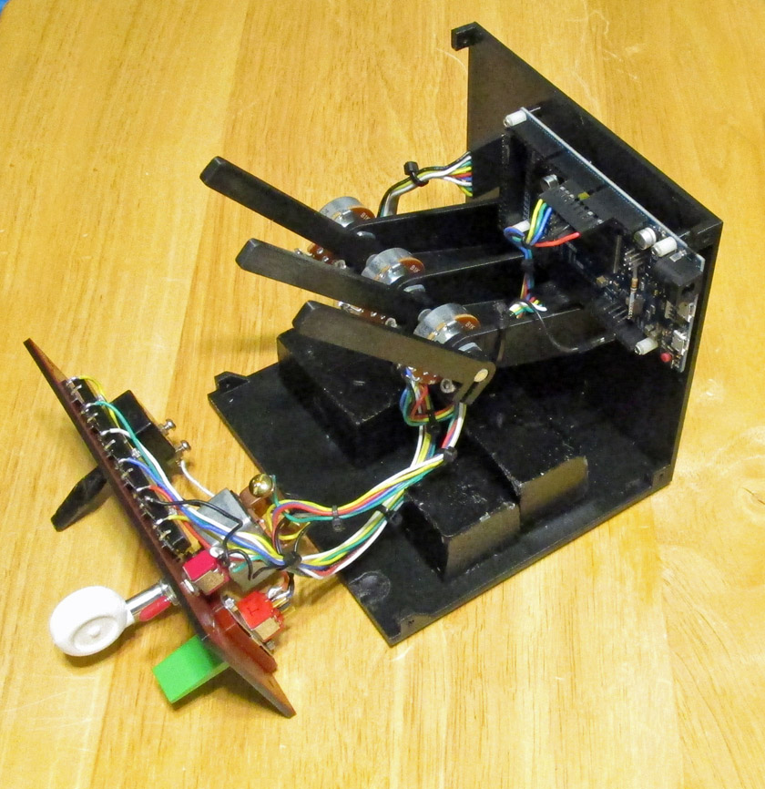
Here is the completed assembly less the covers. You can see that
my "saved" black filament lasted for about 3/4 of the switch plate.
I had a problem with the weight of the knobs causing the levers to
sometimes drop to the bottom on their own. The pots I used on
this version were
much easier to turn than the first ones. After looking at several
solutions, some of them quite complicated, I recalled that simpler is
always better.
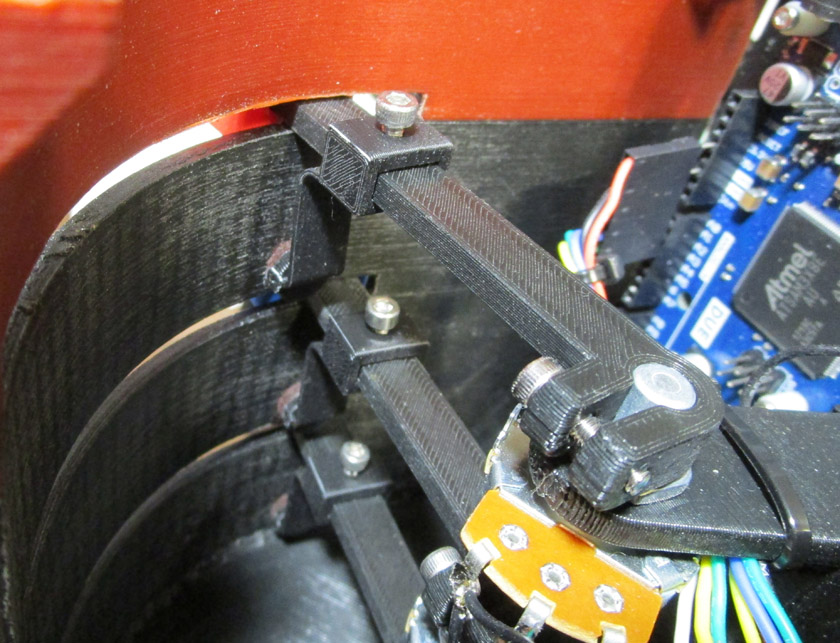
I then designed and built 3 slide-on parts that hold a felt pad,
slightly spring loaded against the inside of the cover. These
work great and can
I add a Trim Wheel:
OK, I'm not done yet!
One of the problems I have found during flying is that the electric
trim switch on the yoke lacks having the "feel" that I like when
trimming the aircraft. Also, the trim wheel in the cockpit is at
the very bottom of the panel and is even farther to pan down to see
than the autopilot, so I cannot see the line indicating the current
state of up or down trim. There is a mark to line up for takeoff
trim, and if you ignore resetting this before takeoff, you can create a
very unstable and dangerous flying condition. The bottom line is
that I decided to add a trim wheel to my quadrant assembly.
The way I did this was to make a narrow housing the same profile as the
main housing, attaching it to the left side with longer screws
to the same holes the cover previously used. This extension
contains the trim wheel, with a gear on the side which drives the
encoder or potentiometer as the wheel is turned. The pair of
gears allowed me to position the sensor where there was more room, and
allowed me to adjust the ratio.
The trim wheel addition consisted of a housing, the wheel with gear, a
flat mounting plate, and an adjustable small plate to mount the pickup
device, and its gear.
Note:
I am including this next section mostly for my own purposes of
documentation, and if you are not concerned with the gory details, skip
ahead to the label "End of technical details".
My first approach was to drive a rotary encoder so it rotated 3 times
the speed of the wheel using a 60 tooth gear on the wheel and a 20
tooth on the encoder. I needed this gearing to get a suitable
number of counts per wheel revolution, as the encoder only has 20
counts per turn. I initially programmed the Arduino so that the
count returned by the encoder (range 0 to 1023) was sent directly to
X-Plane as the trim location. This worked very well except for
one major problem. Since the plane's trim was constantly linked
to the position of my wheel, when the autopilot tried to change the
trim it all blew up. You cannot have two different sources controlling the
trim simultaneously!
To try to work around this situation, I changed the program to merely
simulate pressing the switch to move the trim, so as to not have any
control other than during a move. This would avoid a conflict
with the autopilot. As long as the wheel was moving, the trim
advanced at its fixed rate. This resulted in the trim operating
exactly as though I was pressing the trim switch on the yoke, except
the movement of the wheel simulated the pressing of the switch.
For slow, short trim changes, the effect was quite realistic, but fast
or long changes were definitely not, as the aircraft trim wheel would
run much longer than the duration of turning the new trim wheel.
Also, there was an occasional condition where the plane's trim would
keep moving slowly after it should have completed. This was an
absolute disaster as the plane would soon become uncontrollable!
I think this was caused by the encoder coming to rest with its contacts
in a non-normal position for parking due the the detent not being able
to reliably position the added load of the wheel. Another lesser problem
was if the wheel was turned too fast, the system could not keep
up. This was far less serious, because if it lost part of the
move, it was fixed by just moving it more.
Not seeing a way out of these problems, I decided to replace the rotary
encoder with a potentiometer. As the wheel in the plane turns
about 10 full turns stop to stop, I either needed a 1:10 gear ratio
(actually a little more, as a pot only turns about 3/4 of a turn), or a
10 turn pot. I dug through my accumulated parts and found a 10
turn pot in a suitable resistance range. This is a standard 3/4
turn pot which has a built in planetary ball reducing system, resulting
in it requiring 10 turns to cover its range. I reprinted the trim
wheel with a 40 tooth gear and made a similar gear for the pot.
For the software I just wanted to compare the current position of the
trim to the desired position I had just set and move the trim
accordingly. As I had no feedback on the current position of the
aircraft trim, I simulated it by measuring the constant speed of the
electric trim, then matching it by keeping track of the exact total
time it ran in nose up trim and subtracting the exact total time it ran
in nose down trim. As X-plane always starts with the trim at take
off position, which is mid scale, I also started with the Arduino trim at mid
scale. This worked very well, as all I needed to do was to
drive the position of the plane trim to the same position as my trim
wheel. Functionally this worked very well - except ...!
There was one problem I had trouble solving: As long as the
autopilot was not run, everything stayed in perfect synchronization,
but if the autopilot changed the trim, I was off by that amount.
This was not a problem as long as I stayed in the range of the 10 turn
pot, but I had no way of centering the wheel mechanically.
Electronically it was always centered at the start of a flight, but as
time went by, there was always the chance that I would run into the end
of the pot and nothing would work. I looked at various ways of
allowing the pilot to mechanically center the wheel periodically, but did not really come up with anything desirable.
In the process of working with the encoder earlier, I had come up with
one encoder library which counted every contact transition, not just
complete cycles. This yielded 80 counts per turn instead of the
normal 20. This plus the fact that I had the potentiometer system
working so well brought me to the conclusion that I could use the
encoder instead of the pot, but use exactly the same logic. The
program only required a couple definitions and a single line of
functional code to be changed. Now it worked just as well as with
the pot, (actually better as there was no jitter) and there was no end
of travel to worry about as the encoder can rotate in the same
direction indefinitely.
The ratio between the encoder and the wheel was not mathematically
correct, but close enough at 1 to 1, so I used the same trim
wheel. I had to reprint the encoder
adjustable plate and the encoder 40 tooth gear, put it together, and
it works great. I have found no problems with this solution,
except for the limitation that affects all techniques, that if I move
the wheel faster than the electric trim moves the plane wheel, the
plane will continue to move its wheel until it is in the correct
position. I have moved the wheel very fast and the logic appears
to keep up and I have noticed no other problems. I will stick
with this solution (until I find a better one)!
End of technical details
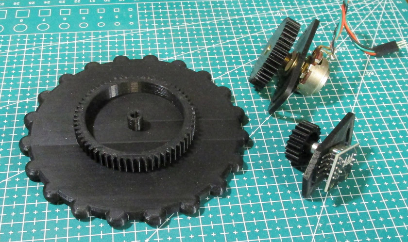
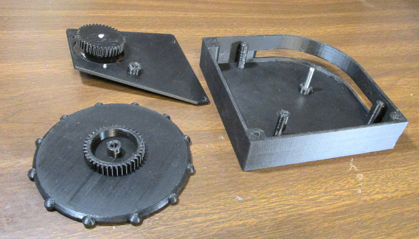
The parts left over after the first two unsuccessful tries were a trim
wheel with 60 tooth gear, an encoder adjustable plate and 20 tooth gear,
and a 10 turn pot, its adjustable plate, and its 40 tooth gear.
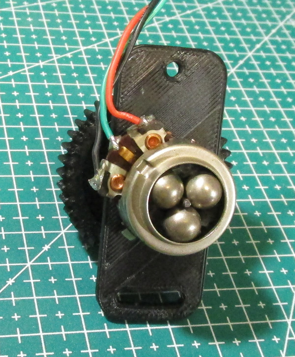
The right picture shows the ingenious friction planetary drive of the
10 turn pot. The
tiny shaft in the center drives the balls and their carrier (and the
pot wiper) around at less than 1/10th the speed of the shaft.
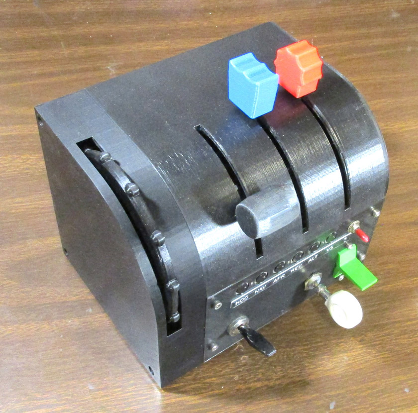
And another version of my "final" quadrant now includes a trim wheel!
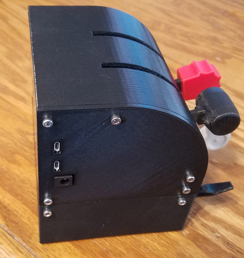
Repair/improvement of quadrant (July 2020):
The Arduino board used in the quadrant has two micro-USB
connectors: The top one (as mounted here) is for programming the board and the
bottom one for communication with the computer during operation.
I noticed that periodically during use, that my connection with the quadrant was dropped
and it would not respond. Changing the USB cable helped for a
while, but an inspection of the socket showed that the metal shell
around the connector was deforming. Steady day to day use, or
even just a non-connected cable was damaging the connector. I
decided to order a few type B connectors as used on printers and
scanners. Once they came, I removed the side plate to see how
much trouble I would have soldering the 4 needed wire
connections. As I removed the plate, the expanded connector shell
caught on the clearance hole and the connector was pulled completely off the
board! Now I had to do something!
It was tricky, but after I determined which pins of the connector
needed to connect to each of the tiny pads on the board, I succeeded in
connecting them all to slightly larger components that were connected
to the correct pins, and wonder of all wonders - it worked. As
the new connector was just a bare metal tube on the outside, I designed
and printed a part that let me mount it with a pair of screws. A
little hot glue to secure the delicate solder joints and it is running
well, with a much more durable connector. The programming
connector still works and hopefully will continue to do so, as it gets
used only if I need to update the program on the board.
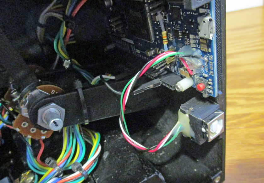
The new much larger and more durable connector replaces the damaged
connector, which is now missing. The remaining micro-USB
connector is the one used for programming the Arduino.
I replace my yoke assembly May 2020
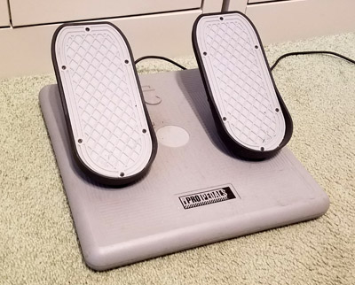
When I started this project I needed some basic
aircraft simulator controls. I found a very inexpensive flight
yoke and rudder pedal pair on Ebay for a very good price. Both
pieces required some minor repairs - sold with full disclosure. I
purchased them, repaired them and used them throughout the early stages
of the project. I did not particularly like either of them, and
after a few months I purchased the finest reasonably priced yoke
available, the Honeycomb Alpha. Online reviews of this yoke
praised it for its quality build, realistic flight characteristics, and
its price, comparing it to units costing 3 to 4 times its price.
Some time later, after also replacing the rudder pedals, I sold the
initial yoke and pedals for exactly what I had paid for them!
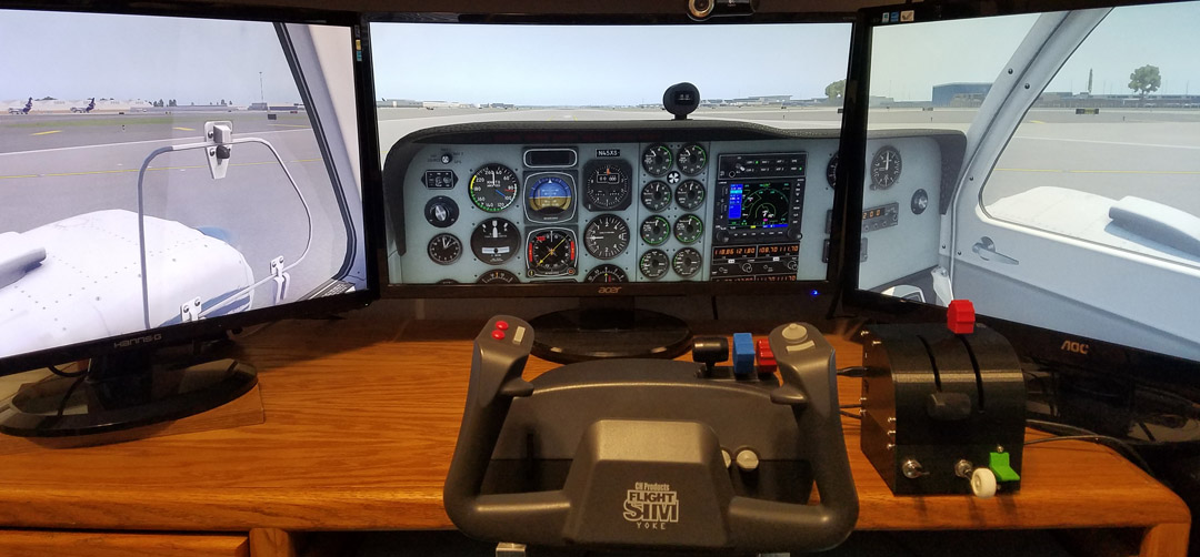
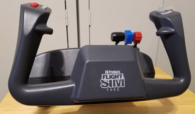
I am totally pleased with my choice of yoke! It is very well made
with a low friction steel shaft providing very realistic motion and
forces typical of a small plane. The wheel turns a full 90
degrees each way, twice what other low price yokes provide, and it
provides a good selection of buttons and switches which can be assigned
to many tasks.
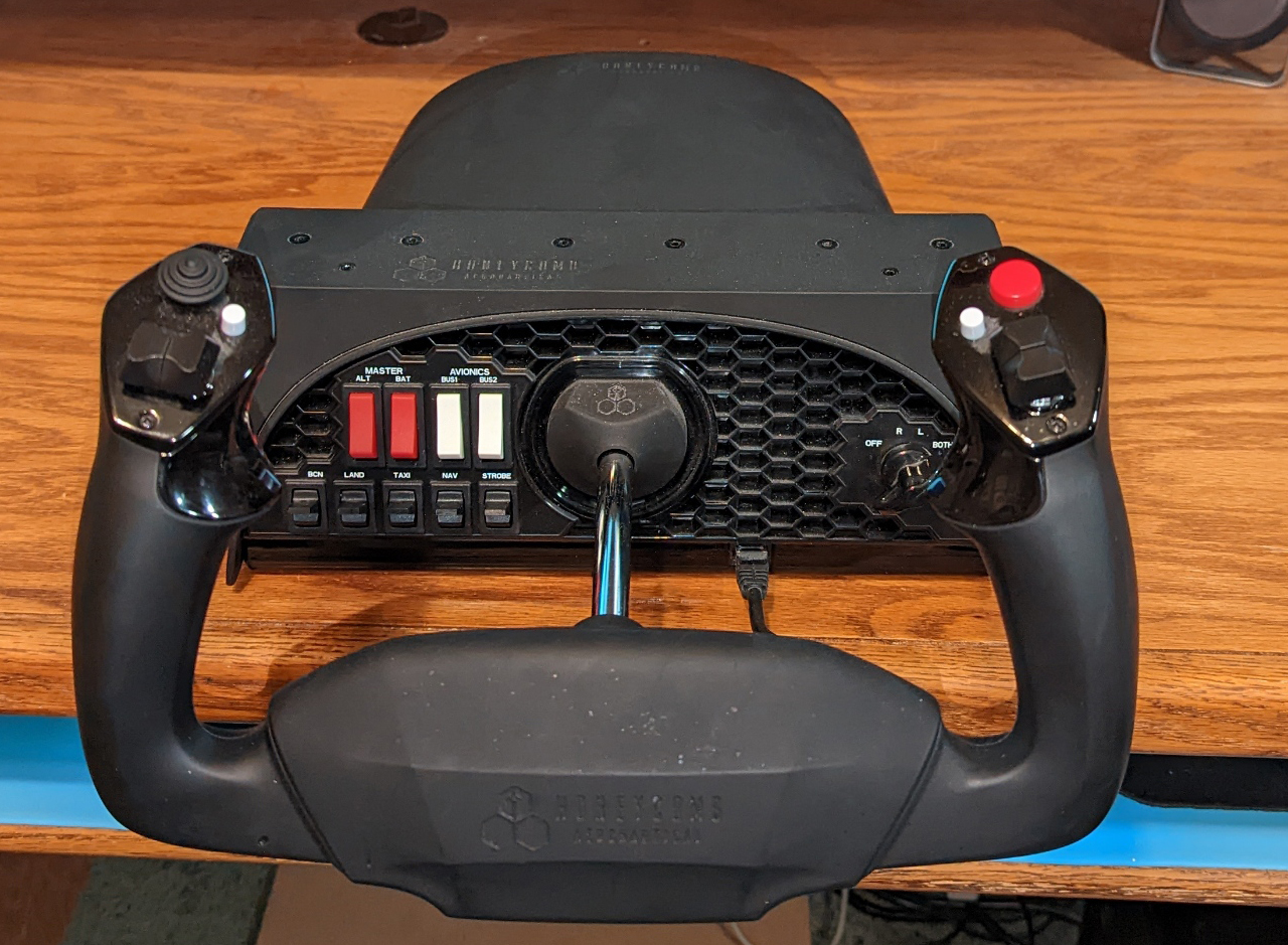
The Honeycomb yoke is a joy to use. In addition to a great feel, it includes light and power buss
switches, a magneto control/starter switch, and a good selection of useful controls on the wheel.
Building an instrument panel:
I am quite pleased with my basic controls now. My quadrant
switches and controls, combined with those on my yoke, (which I
recently upgraded to my dream yoke, the Honeycomb!) provide me with
pretty much all the physical switches, buttons, and levers I
need. The remaining ones should all be OK as virtual ones.
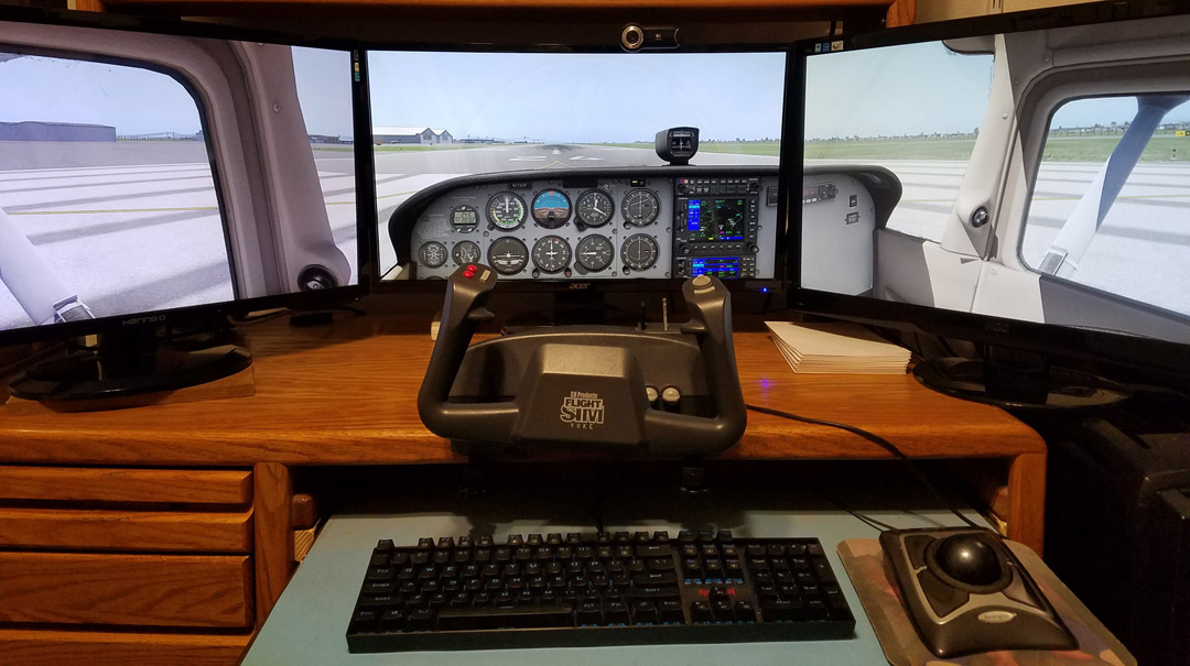
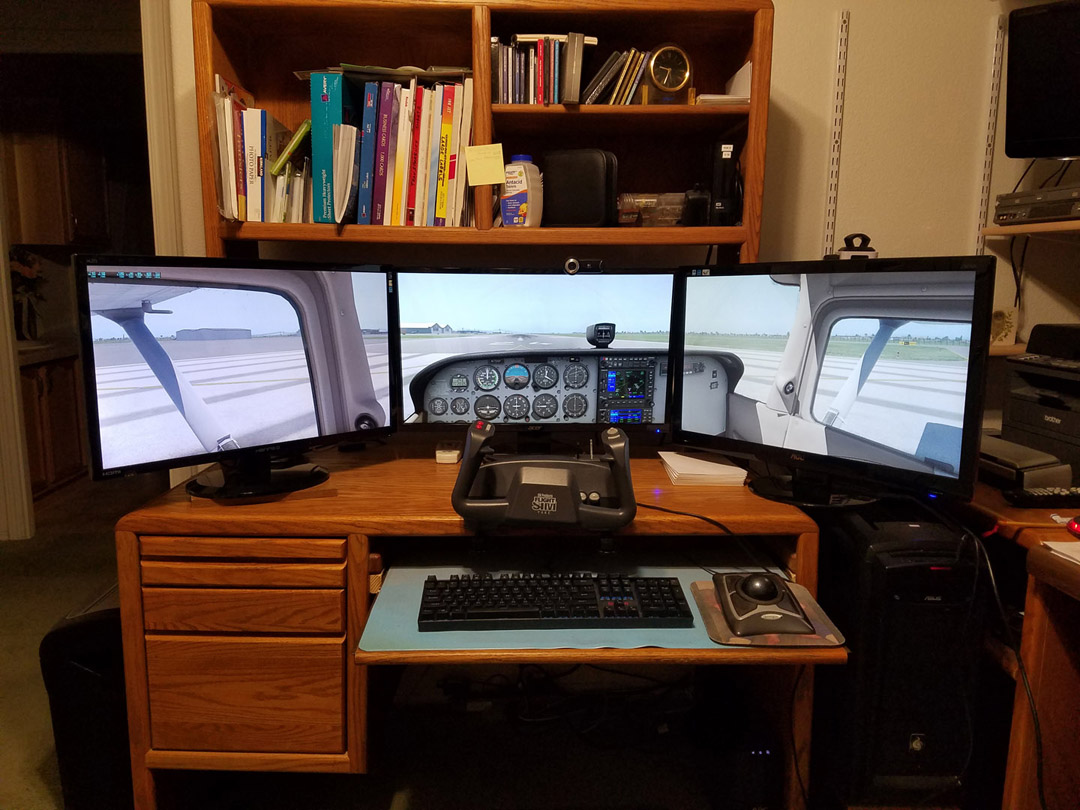
What I am really missing at this point is the ability to see all the
instruments, electronics, and controls on and around the instrument
panel. The basic view gives me flight instruments and radios, but
does not cover things like transponder, autopilot, flaps controls and
indicators, and the trim indicator. These are all below the
normal view and I must rotate my view to see them, resulting in losing
my visibility out the windshield.
Many ardent sim builders decide on an airplane and proceed to build
physical models of the cockpits, some of them accurate to the
extreme. The realism this provides is
hard to beat, but ties the pilot to that specific plane. Another
approach which is infinitely more flexible, although less realistic is
to make a panel with 1 or more monitors, often touch screens, which can
display whatever combination of instruments and controls is
desired.
A program called Air Manager was produced just for this process.
With it, you can build pretty much any instrument panel and
automatically link it with your flight simulator so everything
works. With just a couple of keystrokes, you can then set up for a
totally different airplane. The program is really
marvelous! It comes with a number of pre-made instrument panels
and over 600 instruments you can pick and choose to design your own
panel. You can also design, draw, and program your own
instruments from scratch (if you are skilled). In addition, there
are a large number of additional panels and instruments available for a
nominal cost. I just bought the complete panel for the Cessna
172 for 10 euros ($11.71 with exchange rate and Paypal's cut) to get me several radios
and electronic packages not included in the supplied version.
My plans are to build a cockpit panel holding two 15.6
inch touch screen monitors. These should nicely hold just about
any combination of instruments, radios, navigation gear, and indicators
desired. I will make an easy-to-install mount for the panel and
include provisions for holding my yoke and quadrant as part of it.
I started by looking briefly at the various monitors available that
looked appropriate for this task. Taking the dimensions, which
were pretty much all about the same, I designed a wooden frame, a
mounting panel, and the necessary base to mount to my desk and hold my
other controls
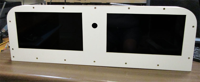
Upon getting the panel parts built and some parts painted, it was time
to order the monitors so I could make accurate cutouts to mount them.
The frame uses 2x2's on the bottom and sides, and a 1x2 on the
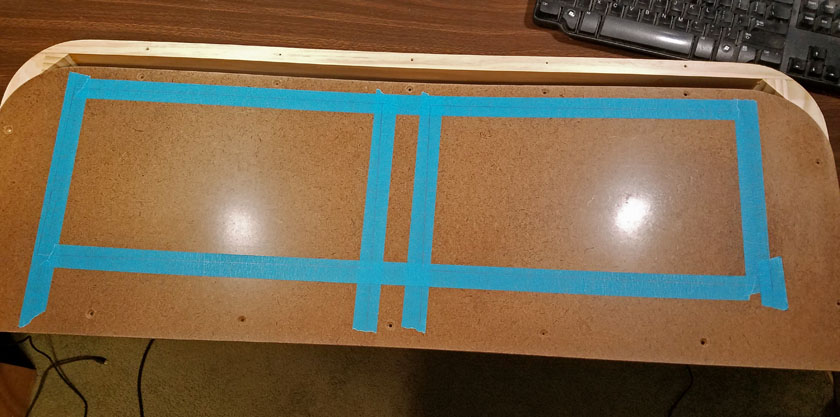
top. The panel is made of 1/8 in. thick tempered hardboard,
similar
to, but not as good as, (in my opinion) the old Masonite that is no longer made. (I may be a little partial!)
Here I have marked the cut lines for the monitors on the masking tape.
This was done after several rounds of measuring, re-measuring,
calculating, and re-calculating.
Fiasco with the monitors: (Warning! Long and tedious discussion follows)
I reviewed about a dozen monitors on Amazon and Ebay, ruling out the
more expensive and the cheapest ones. From the remaining units I
selected one that was an average price, but seemed to have slightly
better brightness and response speed than the others. Out of a
sense of caution, I ordered only one so I could evaluate it before
buying the second one. While I was waiting for Amazon to deliver
it I received a discounted offer for the same monitor from an Ebay
vendor from whom I had made an inquiry, and the offer was only good for
48 hours. As the price was a fair amount less than Amazon, I
decided to chance it and ordered it also. I now had my two
identical monitors on order from two different vendors.
Well, the one from Amazon arrived and I could not even get it to turn
on with the connection method I need. It worked just fine using a
USB-C cable to my laptop, but the input I need for my setup, HDMI and a
separate power adapter, did not even power up. After fiddling
with it for a while, I somehow got it to turn on and it worked great! .
. . for about 15 or 20 minutes. I was never able to turn it on
with that connection again. After spending a fair amount of time
on the phone with Amazon Customer Support, we decided to return the
monitor and they would send another.
A couple days later, the Ebay unit came. It responded almost
identically to the Amazon one, except I never got the quarter hour of
operation. I exchanged emails with the vendor for several rounds
and finally he said he would contact an "expert" and we could probably
get things working. I thought a request he made in one of his
emails was interesting: "Please send me a photo of it not
working". I sent several. I did eventually get it working,
but more on that later.
The next day the replacement Amazon unit came. All three monitors
were truly identical, all were shipped from Kentucky (in spite of the
Ebay ad stating the item location was northern California!), and all
were poorly packed! Each had an inner box very nicely lined with
foam surrounding the monitor. This was placed in a larger
shipping carton with 3 to 6 inches clearance in all 3 directions,
padded with one small raft of munched paper which did nothing.
The Ebay unit was in the same size box (it even had the Amazon curvy
arrow on it), only without the small raft of paper. As I picked
up the first monitor's box there was a loud "thunk" as the inner box
slid to the other end and crashed to a stop. I didn't let that
happen again!
I connected up the 2nd Amazon unit and amazingly, it powered up the
first try! Hey, one out of 3 ain't bad! I continued to test
all the modes and everything appeared to work. I hooked it up to
my simulator and Air Manager and flew using those instruments.
They were bright, clear, and all worked just like they should. I
did shut it down briefly to re-boot my computer and I could not get it
to turn on again. After I let it cool down for a while, all
worked again. This was the only glitch I had. I was not
able to get the touch screen working using the cable they said I need,
but when I tried a USB-C cable that plugged into my computer with a
standard USB end, even the touch screen worked! I was
ecstatic! I had a working monitor! --I thought. It turns
out that upon closer examination, the touch screen did not work as well
as I thought. I kept getting a strange pop-up on the right side
of my screen and discovered that the touch screen was acting as if I
were continuously touching a spot at the very right edge of the screen
near the top. When you touch the screen, it puts a light blue
circle around the spot you touch. There was a continuous half
circle at the edge of the screen. It also made the computer act
very unpredictably.
From what I learned on Amazon #2 I got the Ebay machine running quite
well - mostly. I had made an error: I read the manual and
connected it the way they said to! It said to connect the power
supply to the bottom USB-C, connect the HDMI cable, and if I needed the
touch screen, connect the micro-USB. I did all that. All
the monitors worked just fine connecting only the upper USB-C to my
laptop, so I thought I would try connecting that with a USB-C cable that would connect to my computer. It now
worked! I wonder if the returned Amazon unit
would have worked. It still is not 100%, though, as I have not
been able to get the touch screen working with the HDMI setup, which I probably could with more time spent. I
know it basically works, as it is fine with the hookup to my laptop.
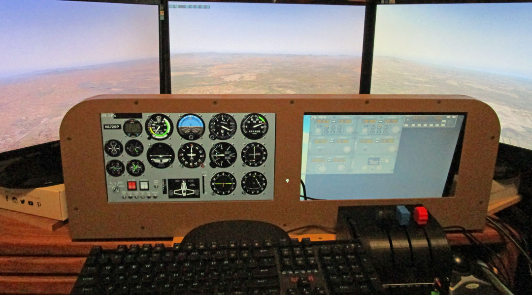
After I got a monitor working for everything except correct touch
screen operation, I mounted it in the left side of the panel.
Just for kicks, I
propped up my smallest old computer monitor behind the right
cutout. Using Air Manager I put the Cessna instruments on the
left and some 737 radios
on the right. You may notice a slight quality
difference (ha!). The touch screen panel is an IPS display with about
178 degrees of readable viewing
angle. The old monitor is lower resolution to begin with, and has
a very narrow angle of good viewing. Looking directly at right angles to the screen
it was much better than in this picture, but was still no match for the IPS panel!
In the morning I actually thought I might have 2 monitors to keep and
use. I wanted to re-try the Amazon one to see if the touch screen
problem was short or long term. Sadly, it was still there.
Time to return the two remaining monitors and start shopping for a
different brand! There is no way I could trust any monitor of
this brand!
Note from about a week later! All 3 monitors have been shipped back to
and received by the vendors (in the same boxes, but properly packed!). I have received all my refunds!
New monitors ordered:
I have now ordered two totally different monitors from Amazon to
replace these. They were promised in 4 days, but the tracking
indicates I may get them tomorrow which is 2 days. I picked these monitors for several reasons:
1. They are obviously a different design. Most
of the ones offered are similar enough that they may be the same with
different brand names, and I don't want any possibility of getting the
same design as before.
2. This monitor uses full size HDMI and USB ports instead of the mini HDMI and the microUSB on others.
3. They have a US website with English speaking support.
4. User reviews were positive, including examples of using it in the same manner as I need.
The one con, which I realized immediately, is they are slight larger in
all 3 dimensions. The extra 1/4 inch in height means that the
screen will not line up with my existing cutouts. The extra 1/2
inch in width means there is not enough room left to plug in the
connectors the same way I was previously going to, and the extra 1/4 inch of
thickness is fine. It is this dimension that allows full size
connectors. I have come up with solutions for all these problems,
but it will involve a little rework to the frame, and making a
new panel with cutouts to match the new monitors.
The agony continues:
I had been given a 4 day delivery time from Amazon for the new
monitors, but the box arrived after two! I anxiously took it in
and opened it. In shock, the first thing I saw was 13.3 inches in
big print on the top box inside. I panicked and ran to verify
that I truly ordered the 15.6 size - I had. I then looked again
at the product box and saw that it wasn't even close to what I
ordered. It was a pair of very nice DVD players!
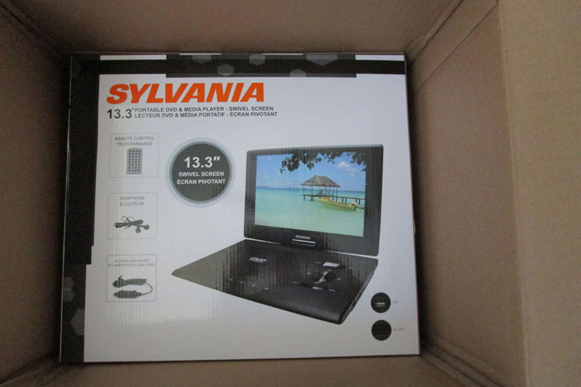
This is the very disappointing sight I had when I went to see my new monitors
The problem really was not Amazon's fault. They were shipped from a
big name 3rd party in New Jersey, but the Amazon customer service agent
felt bad that I had been having so much trouble trying to buy my
monitors, and he issued me a courtesy store credit for far more than I
would expect, if I expected any at all! That was very nice.
He re-ordered them for me on an exchange basis, issued me yet another
prepaid shipping label and again quoted 4 business days for
delivery. I just received an email from UPS stating it will be
delivered tomorrow (2 days). I guess I was paid well enough for
another 2 day delay, and actually I am receiving the replacements on
the day originally quoted for the previous round.
The final word on monitors (I hope!):
Well, at last the maddening monitor merry-go-round is over! I
received the two replacement monitors, they were truly what I had
ordered, and they both worked right out of the box(s) - even the touch
screens. In addition, I was able to hand the UPS delivery man my
return box and did not even have to drive halfway downtown to the UPS
store to return the wrong ones. Yay!
The DIY Knobster:
One of my favorite flight sim Youtubers, Russ Barlow, an
ex-military
pilot, an ex-airline
pilot, and now retired, is an avid simmer. He is very intelligent
and
knowledgeable about electronics, programming, and allied fields. One of
his videos is what inspired me to build the touch screen panel.
Russ is a big fan of touch screen and loves the Air Manager software,
but got very annoyed when it came to
turning knobs on the instruments and radios. Most touch screen
actions are very natural such as touching a push button or swiping a
switch up or down. Air Manager's solution to rotary controls is
to first touch the desired knob, which shows a blue highlight, then
use your finger to draw circles around it in the
direction you want it to turn. This is a good solution, but is
not close to real life when adjusting various settings. Probably
the greatest objection is that you have to keep your eyes on the
monitor continuously while making changes or your finger circle will
probably move out of position. Russ did some experimenting trying
various switches and rotary encoders, and after several iterations
developed a device now called the Knobster. This is a double
rotary encoder with push button. It is a device
with a large knob in the back and a smaller one in front, and pressing
the front one works like a push button. He convinced the Air
Manager people to support it and now it is a much easier and more
realistic control. If, for instance you want to tune a radio
which uses the large knob to tune whole frequencies, the small knob to
tune the decimal portion, and the push button to perform another
function, you first touch the desired control on the screen, which
turns yellow. You then turn and press the knobs exactly like you
would the real control in an airplane and all its functions work.
Once your hand is on the knobs, you are free to look away at the
results of turning the knob, at other instruments, or outside.
Not wanting to run a production shop, he turned his invention over to
the Air Manager people in exchange for a small license fee per unit
sold. He also released it as an open source project.
Air Manager provides the links to instructions to build your own, which
is what I did. I could have bought a complete unit for about
$130, but instead bought the rotary encoder and an Arduino Nano for
about $40 and built my own.
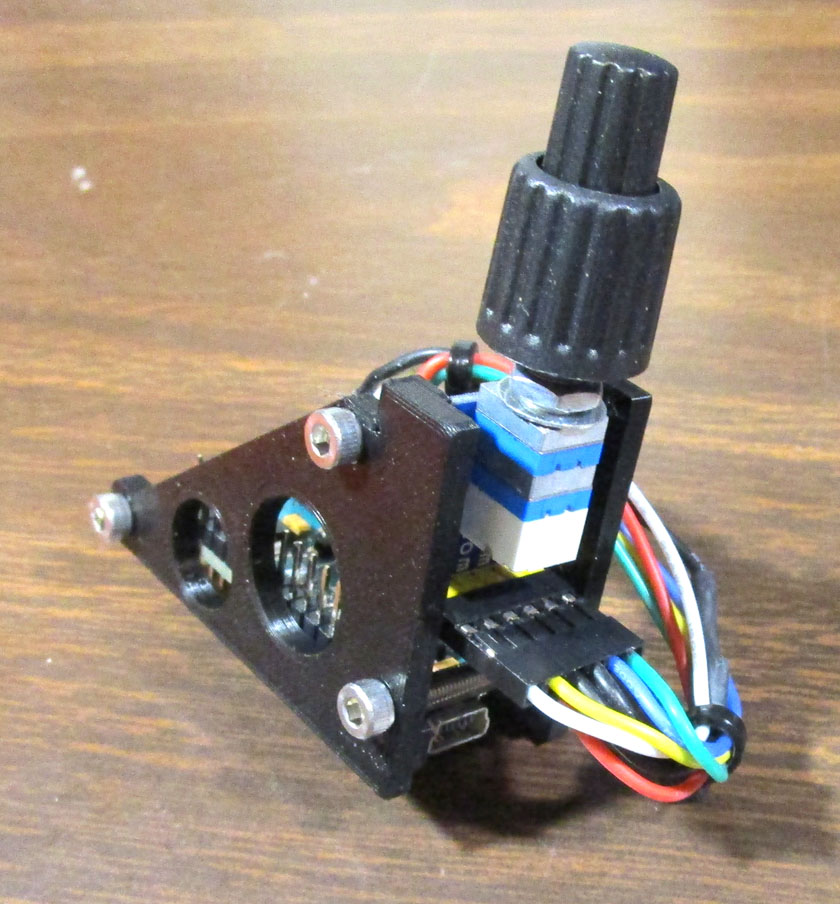
This is my DIY Knobster. The encoder came with a small circuit
board which is positioned vertically on the right The Arduino
Nano is
across the bottom. A small 3D printed framework holds the boards
together. The threaded bushing under the knobs
mounts it to the panel. The mini USB connector on the
Arduino at the very bottom, under the knobs, connects to the computer.
Modifying the panel:
Since the new monitors have slightly larger case dimensions (the screen
size is identical to the previous ones), several things did not work
anymore. I could not properly align the screen with the cutouts
any more, even the modest increase is size prevented me from having
room for some of the connectors, special cutouts in the frame no longer
align with the connectors needing extra clearance.
My first task was to figure how to mount the larger monitors in the old
frame and be able to plug in all the needed cables. Since all the
connectors on these monitors are on one edge I needed no clearance on
the other. There was no way I could place both monitors and the
connectors plus a reasonable cable bend inside the existing
frame! I ended up notching the vertical frame member on the left
side to provide an opening large enough to plug in the cables right
through the frame. Of course I had to patch the notches already
in the frame first. By placing both monitors tight against the
frame uprights there was plenty of space for connecting the right hand
monitor in the space between them.
It was clear that I needed to replace the front panel to get
differently positioned holes. This time I bought a panel of
dry erase whiteboard material. This is fiberboard with a sheet of white
plastic laminated on the front, and a sheet of black on the back.
It gives a much better surface and testing on a small sample I found
that one coat of paint covers it quite well. The raw hardboard
took 3 coats as the first ones soaked in.
I spent hours measuring everything and laying out the cutouts.
For some reason, they just did not quite line up correctly. I
finally decided that Youtuber Russ had a pretty good idea. He cut
a piece of cardboard exactly the size of the monitor case, carefully
marked the display size on it and drilled small holes at each corner of
the screen. He then positioned the cardboard exactly
where he wanted
the monitor and using his cardboard holes for alignment, drilled
through the front
panel. Drawing lines on the panel between the holes now gave him
his cut lines. I did exactly the same thing,
except I used a scrap piece of the first panel hardboard instead of
cardboard. It came out as well as the first panel where I
measured carefully then used the mill to cut the opening. That
could have been a problem as the openings are larger than my mill can
travel and I had to cut half then turn the panel around and try to line
it up accurately to cut the other half, and repeat for the other hole. The original panel cut
left a fuzz on the edge that made it impossible to accurately line
up the second setup. Sanding and filing later removed the fuzz
and slight misalignment, and
left a nice surface. I had to block sand the
edges of the new panel to even out my hand guided scroll saw, but it
worked well.
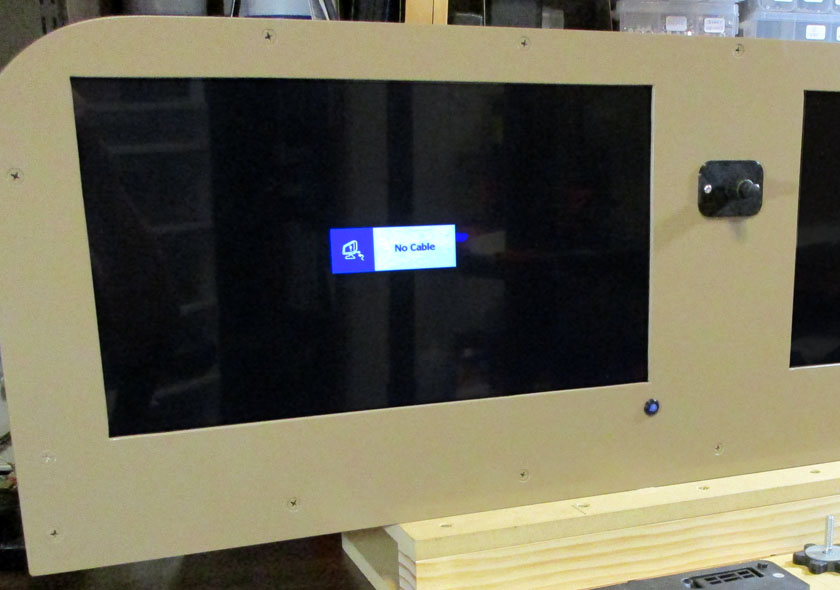
The assembled panel looks somewhat nondescript with everything turned
off. Both monitors are mounted and the hole in the center is for
the mounting of the Knobster. I have delayed painting it as there are still a couple of holes to add.
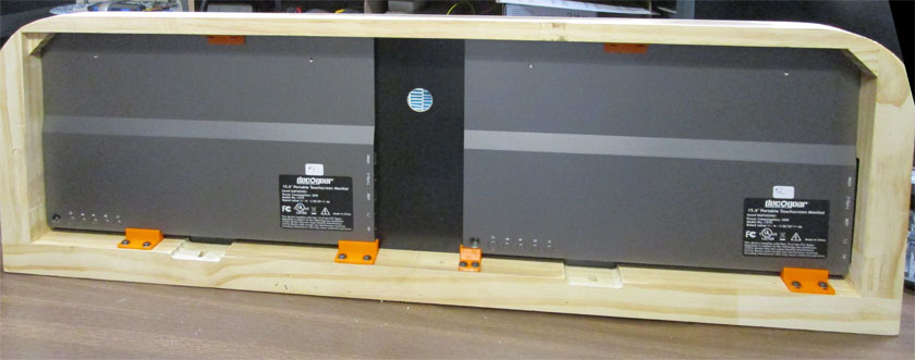
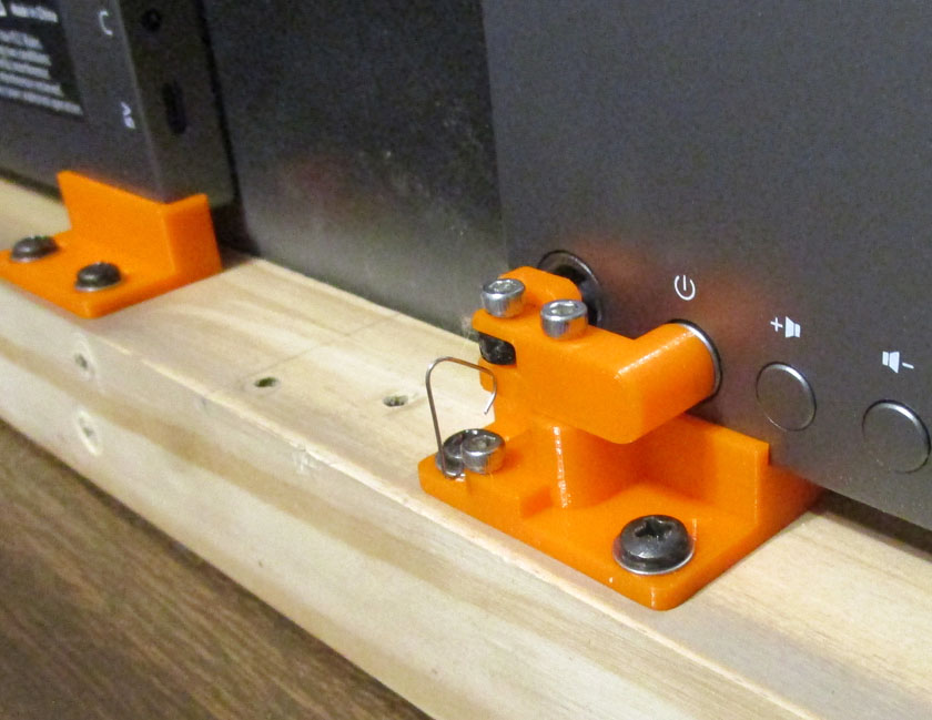
3D printed clips at the bottom space the monitor 3/8 inch off the
bottom, and assure its proper placement. Clips at the
top
simply hold the monitor against the panel
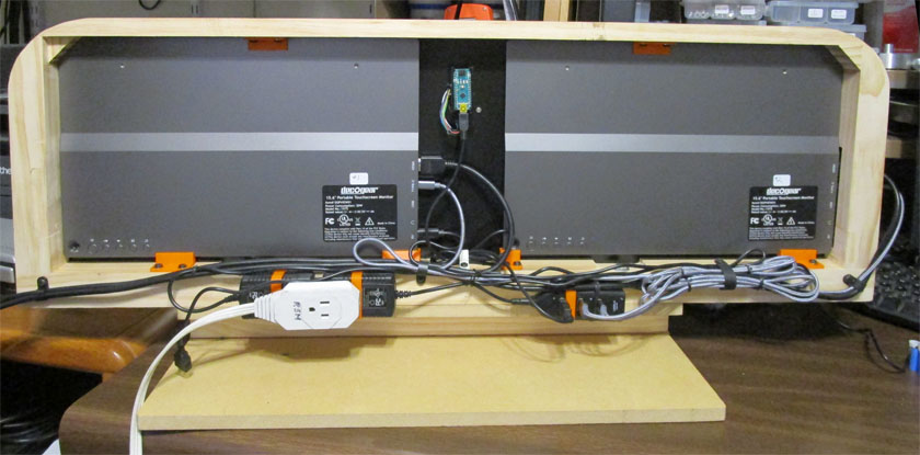
Then came the wiring. Cable management was difficult. If
only my cables were the right length! The two power
supplies for the monitors
are strapped to the bottom frame member the correct distance apart to
plug into the double receptacle of an extension cord. A USB hub
is also strapped similarly and accepts the USB touch screen output from both
monitors and the Knobster. Only 1 USB cable is needed for
connecting to the computer this way.
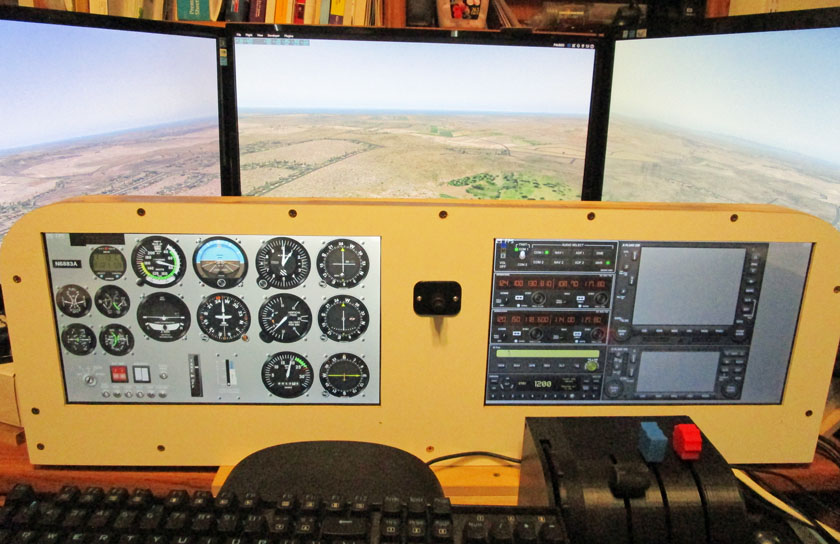
This is the first time I have had it all set up in a flyable
condition. I flew it for over an hour and love it! It is so
nice to have large clear instruments
close where they should be! And I think I have everything I need
to see visible now. If I find something else I need, it is a snap
to add it.
The two GPS receivers on the far right do not display yet. There
are two overall connection schemes that allow placing the live image in
the Air Manager screens and I have not decided which to use yet.
It is low priority! After this picture was taken, I removed them
from
the right panel and enlarged the other electronics to mostly fill the screen for now. Changing is so easy!
Now that I have it all together and working, it is time to take it
apart! I am reasonably confident that I have identified any
additional front panel holes needed and put them in. It is time
to paint! I also ordered some shorter cables to eliminate most of
the massive bundles. While I wait for the paint to harden and the
cables to arrive, I have another project described below.
Monitor behavior:
These new monitors are great, but there are a couple of idiosyncrasies Don't get me wrong, I love these monitors. As a matter of fact,
the original monitors may have acted exactly the same, but I never got
far enough with them to know. The main problem is
with the on/off switch. The monitor does not switch between
standby and on when there is a video signal. You must manually
turn on the monitor when ready to use it. Probably the primary
reason for this is each monitor contains an internal battery capable of
operating it for about 6 hours. This is a great feature for which
I have no current use. I was initially afraid that I would have
to always turn them off when finished or chance draining the batteries,
but found out that after one minute of no signal, they do turn off
automatically.
The monitors also have an interesting feature. There is a hole
through the monitor in the lower right corner designed so you can stick
a pen or pencil through to use as an impromptu stand. This hole
also is surrounded by clear plastic which lights up when the power is
on. This will all tie together soon, trust me. Another
annoyance for my use is that the power button is on the lower rear of
the monitor right next to the illuminated prop-up hole, hard to reach with my mounting system.
With these facts in mind, I set about to design a front panel on-off
switch for the monitors. After several rough design thoughts, I
arrived at a plan to have a plexiglass rod pass through the front
panel, through the prop-up hole and press on one end of a pivoting
bar. The other end of this bar would press on the power
button. A benefit of this plan is that in passing through the
illuminated hole, the clear rod picks up enough illumination to provide
an indication at the front panel when the power is on. After I
designed all the pieces and printed them, I put it all together and
wonder of all wonders, it works great!
Here is the power on/off mechanism: The plexiglass rod comes from
the front panel through the hole in the corner of the monitor. It
fits into
a small printed clevis attached to the left of the pivot bar. The
bar is free to swing around the screw in its middle, and as it rotates,
it presses
the power button on its right. Actually the bar can only pivot a
few degrees, as at rest it is spring loaded against a stop block, and
when pressed,
it can only rotate by the short travel of the power button. The
base of this mechanism is a retainer for mounting the monitor, having a
shelf
to hold it up in light contact with the top frame, and a retaining lip
to keep the monitor from moving back or left, similar to the block on
the left.
Each monitor has a small power button which is the end of the
plexiglass rod. Here you can see that it glows blue because the
power is on.
This light turns to red when there is a video signal present.
Computer connection changes:
After viewing a number of Youtube videos and reading articles talking
about the frame rate degradation caused by each additional monitor
connected through Xplane-11, I decided I would need to use my secondary
computer to run the Air Manager software and to drive the two touch
screen displays, letting my primary computer run Xplane and drive the 3
main monitors. This worked great! Air Manager and Xplane
automatically connect to each other through my home network and work
flawlessly together. The problems I had are logistical. I
had monitor and control cables running back and forth, I was always
grabbing the mouse for the wrong computer to make a change, and it was
just generally confusing. I was not willing to dedicate my 2nd
computer only to the simulator, nor to even move it to be closer to my
primary one. I was hesitant to just experiment with various
setups, as Air Manager is tied to a specific computer and will allow
only 3 changes to a different computer during the lifetime of the
license.
Before even being able to consider moving Air Manager to my main
computer, I had to see if the system could drive 5 monitors. My
graphics card will drive 4 monitors. If I had no graphics card
and used the integrated graphics capability contained in the CPU, I could
drive 3 monitors. Usually, installing a
discrete graphics card will automatically disable the integrated
graphics. Again I researched and experimented. I found a
BIOS setting called Primary Graphics Adapter. It had 2 choices: PCI Express and Onboard. I
tried each, and by selecting the Onboard I was able to drive my 5
monitors, but with problems.
It turns out that
this was not the correct setting, as having the integrated graphics as
the primary caused several glitches, not the least of which was there
was no way to enter the BIOS unless an active monitor was attached to
the Integrated port. I then saw a Youtube video by Michael Brown
(he owns X-Force PC which does product support for and is very close to X-Plane, but is
not directly associated),
specifically on setting up for more than 4 monitors on an Asrock board,
such as mine. What I had not spotted was another entry which you
had to scroll down to bring it up to the screen. This setting
was IGPU
Multi Monitor. By setting this to Enabled and leaving the earlier
entry set to PCI Express, all seems to be fine. No longer
are the 27 inch monitors switching place in the monitor layout when I
connect and disconnect the touch screen ones, and the BIOS shows up on one of my main monitors. Thank you
Michael! For reference the settings for Asrock boards are as follows:
- Open the BIOS (actually UEFI)
- Switch to the Advanced screen
- Move to the Advanced tab
- Click on Chipset Configuration
- Verify that Primary Graphics Adapter is on PCI Express
- Scroll down to bring up entries below the screen to IGPU Multi-Monitor and set to Enabled
- Exit and save your changes
I then experimented using the Air Manager free trial demo. I
realized that
this should at least give me an idea of the degradation I would see
driving all 5 monitors from my primary computer. The demo only allows a
single panel of the 6 basic instruments, and no obvious way of
displaying them on both monitors. I then discovered that I could
run 2 instances of Air Manager with each feeding a different
monitor. Using this setup and running the released version of
Xplane, my performance dropped from almost 40 frames per second to the
low 30's. Allowing for the added load of flying in areas with
dense scenery, that would probably drop to the high 20's, not ideal,
but probably marginally OK. I then tried their beta version using
the Vulcan graphics driver instead of the previously used OpenGL (the
software that converts the logic into video signals). Most users
are raving about the increased performance, seeing a frame rate
increase of 50 to 100% with this change. Xplane is currently in
the
13th beta version. I have had no problems using it and it is only
getting better. Using the beta version and 5 monitors, I am
getting frame rates in the high 40's to low 50's! This is
great!
Running
the beta version with just my 3 monitors I have been getting frame
rates in
the mid 50's. I then, with all 5 monitors tried flying around LAX, which has very high
density scenery, and the frame rate dropped to the low 30's, more of a
drop than I expected, but still OK.
These tests convinced me, and I burned one of my 3 allowed
"resets" and moved Air Manager. I now have Xplane and Air Manager both running on my
primary computer which drives the three 27 inch main monitors from the
high performance graphics card and the 2 low demand touch screen
monitors from the much less capable integrated graphics outputs.
The performance after fully installing the software matches the results
of my test exactly, and I think will be totally satisfactory.
Thank you Vulcan! I hope the improved Xplane will be out of beta
soon!
The interconnections are simpler now, and using a 6 port USB hub for
all the USB connections on the panel, now there are only 3 connections
and AC power (and even that is optional, as these monitors include a
battery rated for up to 6 hours of use) to be made when setting up the
panel. With the 2
computer system I only used a USB hub for the long run to the 2nd
computer, but I could have gotten it down from 6 to 4 connections with
another hub. The primary advantage is the simplicity of
connection and use. A secondary consideration, but a major one
was that in order to be able to show the more advanced "glass cockpit"
displays, I would have had to buy a second copy of Xplane to run on the
2nd computer (technical issues I won't try to cover here).
Improved Wiring:
As you probably noticed from several pictures back, my wiring was a
mess! I had bundles of wire, to use up the excess length hanging
on the back. I had the two monitor power supply transformers
hanging off the back with an extension cord plugged into them, and,
although it doesn't show in the picture, the connecting cables ranged
up to several feet long. These were always in the way when trying
to stow the panel between uses.
To correct these problems, I did several things:
- I designed and printed a box to hold the power supplies for the monitors, and included a removable power cord.
- I ordered several new cables that were of more appropriate lengths.
- I bought a new 6 port USB hub to replace the 4 port one.
- I completely rewired the rear of the panel.
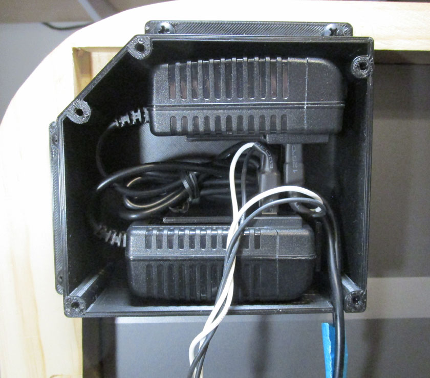
The new power box contains the power supplies for both monitors. They have been wired using 1/4 inch wide
spade terminals pressed onto the AC prongs, then protected with shrink sleeving. They each are connected to a
receptacle which accepts a standard computer power cord. The transformers are held in place by printed walls
which prevent any movement.
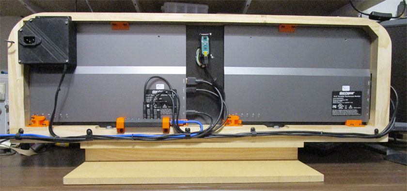
The wiring is now much cleaner! The only loop of excess wire is
contained inside the power box. The new USB hub (to the left of center with 3 cables
looping up to plug into it) now will accommodate the yoke and throttle
quadrant if desired. The 3 wires to my computer (2 HDMI's and 1
USB)
are a maximum of 18 inches long, and can be held out of the way for handling with the hook to the left of the power box.
Addition of 8/18/2020:
Microsoft Flight Simulator 2020 arrives!
The long awaited release of Microsoft Flight Simulator 2020 is
finally here! I pre-ordered the program several weeks ago and
actually installed it (at least a shell of it) at that time. Of
course every time I tried to open it I received a pop-up window stating
that it was too early.
I was actually able to start using it today! The scenery is beautiful! The planes fly well,
comparable to those in X-Plane 11. It is a fairly well polished
program which has some great points and some not-so-great ones.
My initial observations (and opinions) are:
Great points:
- Beautiful, real life scenery based on Bing satellite imagery
-
Good selection of initial planes to fly (20, 25, or 30 depending on your version of Flight Simulator)
- Almost
40,000 airports world wide - accurate, but not highly detailed (but
probably equal or better than any other simulator's without 3rd party
add-ons)
- There are 30, 35, or 40 hand crafted airports (depending on your version) with almost total realism
- Very
realistic flight characteristics - over 1000 points aerodynamically are
calculated per plane, ground terrain used to calculate
local air current disturbances
- Excellent control of the weather conditions including duplication of the real time weather where you are flying
-
Beautiful cloud representations - better than in any other sim I have seen
-
An easy to use user interface - selectable options for various skill levels
- An excellent set of cameras (views) available including drone mode
-
A promise of a rich set of future improvements
Neat features that mean little to me personally:
- Real time weather conditions for the area you are flying. i.e. -
Youtube is full of simulated flights through the recent gulf hurricane
-
Real time aircraft flights - If an airplane is flying over your house, the simulator will show it (limitations apply)
- Multi-player - many individuals can gather to fly in the same area
and all will be seen by everyone. This is a biggie for many game
players, but not for me.
Not so great:
- No multi-screen support - this is my biggest disappointment,
and this alone prevents me from even considering the program as my
primary flight simulator.
- The high-tech glass panels only "mostly" work, but are generally buggy.
- Autopilot
loses control of plane at faster than real time speeds. This is a
problem if I want to "fast forward" over boring parts of long flights.
(X-Plane does fine)
- Default setup data is
missing on many common peripherals (hand programming of each button or
switch, etc. is needed), a one time nuisance (DONE for my setup
8/19/20)
- My quadrant doesn't work due to differences in calibration methods (fixable with programming change) (I FIXED 8/20/20)
- Will not work with my instrument panel or Air Manager yet (Air Manager has promised the update soon))
- Takes
over twice the time to start up as X-Plane - almost 4 minutes, plus
time to select your flight vs. under 2 + setup for X-Plane.
- Numerous new-release bugs - frequent updates planned initially
Note of 11/8/2022:
Virtually all of the above problems have now either been fixed or
improved. The latest revision has finally enabled multi-monitor
use, the Honeycomb yoke and throttle are now listed and install very
easily, an Air Manager upgrade enabled my panel, time to load has
dropped by about 50% for both Xplane 11 and Microsoft Flight
Simulator. The program is maturing nicely.
Expected items (facts of life):
- Mostly new commands to learn
-
Uses a lot of Internet bandwidth and drive space
- Requires a powerful computer with good graphics capabilities - mine is doing fine
In all fairness to Microsoft, a couple of the above problems will
soon be corrected, either by me or by them or one of their
vendors. If MS
keeps their
promise to keep working and upgrading, hopefully most of the others
will be dealt with soon.
The official release of the much hyped program was August 18. Actually I found in one spot of their literature that
it would be released at 9 PM on the 17th. When I pre-ordered it
several weeks ago, they let me install it immediately, but that only
took a few seconds so I knew I had not actually installed any more than
a loader. At about 8:30 on the 17th I tried to open it and still
got the now familiar window stating "You are too early!" At about
9:05 I got right in and started a fairly long sequence of events.
After a few screens needing my input, it started downloading 95.15
Gigabytes of program data. At just about midnight it
finished! I am 4 days into this months Internet quota and have
already used 34% of it! (I hate quotas!) I was impressed with the
download, as for most of the time I was watching it, it was downloading at a steady 120
Mb/sec. My service is spec'd at 100 Mb/sec. It did
periodically slow down to almost nothing while decompressing the
files. Also, I'm sure watching streaming videos in the other room
during much of the download didn't help the speed any!
The next morning, after some mandatory errands, I tackled installing my
yoke, pedals, and quadrant, with far less success than I had in a
similar time on Xplane 11. I ended up postponing this effort and
installed only my original CH yoke, which includes a throttle.
This was the simplest setup I
could fly. I boned up on some of the different commands this
program
has and went flying. Of course the first
thing was to find my house! I am not disappointed! Here are
a few screenshots flying around in Prescott, and one in Escondido,
CA.

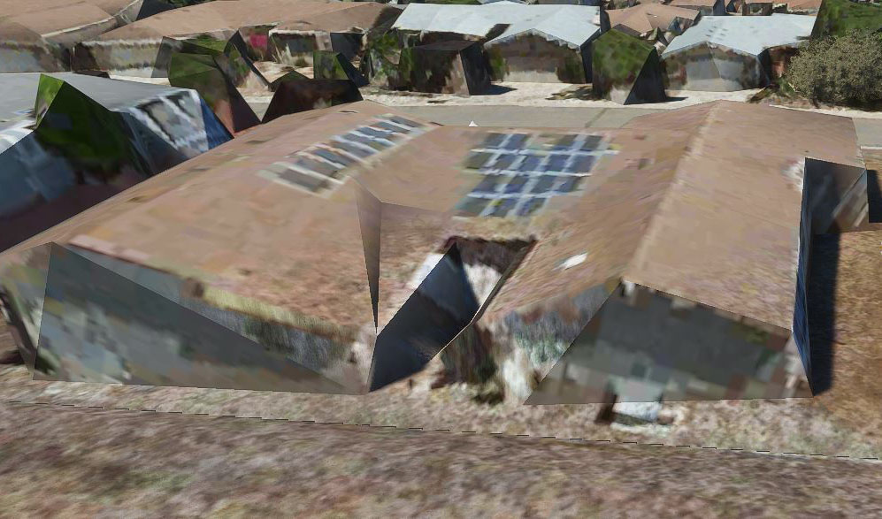
Looking down on my neighborhood, it looks beautiful, and very
accurate (as it was several years ago when the satellite images were taken). However
when you get close you can see some of the compromises the artificial intelligence engine uses to change a single
view 2D picture into a 3D object.
Considering that they did this
to every spot on the planet, I think they did very well! A few areas
of the Earth are created using true 3D images,
obtained using
photogrammetry. (taking multiple pictures from different
directions and combining them into a 3D image) and result in much better
closeup pictures.

This view of my church, the Prescott United Methodist Church looks like a
photograph! OK, there are a couple of glitches in the parking lot
which appear to be poorly modeled cars.

I also (very quickly) flew to Escondido, CA and looked at my previous home. In the last 15
years, the subsequent owners have added a deck and changed the landscaping, but it looks good!
To find my house (or any other place) putting in a pair of
latitude/longitude coordinates and flying to them would have been easy,
but Microsoft doesn't give you a way to do that. A Youtube
presenter who uses the screen name
Squirrel, has made a very helpful series of 5 (10 now, two weeks later) tutorials on getting
starting with the sim, and explains a way to fly to a coordinate.
Basically, you look for a nearby waypoint, and edit the two files
associated with it substituting your own coordinates, and a new waypoint name. Using the GPS
receiver
(which I still need to learn) you then just fly there. My method so far is
just looking for familiar visual landmarks and working my way to my
target location from there. This is much harder than it sounds, or than I thought
it would be. I found my current house this way without too much trouble, but for my old Escodido home, I don't think I
would have ever found it without
Google Earth to use for comparison! I probably should have used
Bing, as that is what all the scenery is derived from!
Note of 9/6/2020:
Microsoft does actually give you a somewhat roundabout way to fly,
actually be transported, to a pair of coordinates. They have a
developer's mode which you have to open, then there is the option of
typing in your lat and lon values. When you exit, the plane is
paused and the scenery below merges into the desired location.
This is still a somewhat non-obvious procedure, but is much better than
having to edit a pair of files! Developer's mode also allows you
to change airplanes in mid-flight!
There are several cameras associated with this simulator. A
camera is really just your view. The cockpit camera gives you all
the views of the instruments and views around and out of the plane, and
is the normal one used during flying. An external camera can be
set to follow your plane and show it from the rear. You can
actually fly using this camera as they give you a "heads up view" of
the basic instruments, superimposed on the screen. This
camera can also be positioned to the left, to the right, to the top, or in front,
always looking at the plane. There are additional slots for
several custom camera views.
They also give you cameras attached to the wing tips looking in, the
tail looking forward, under the tail looking forward, and a couple
others. These are fixed and you cannot customize them.
My favorite camera is the drone camera. When you activate this, it
starts with the same view as the rear view of the external camera,
the difference is that you can fly it from there. Using a totally
non-intuitive selection of keyboard keys, you can fly forward, back,
sideways, rotate, tilt up or down, and fly up or down. My procedure (during my total flight time of slightly over
an hour) is to fly the plane close to my target area and pause it.
It now just hovers in place and I turn on (launch?) the drone
camera. I then fly it to the area I want to investigate closely and
take my shots using Greenshot, a screen capture utility.
I have a LOT to learn about doing a proper installation of my
peripherals and just flying with it. I did find a listing of the
keyboard shortcuts which once I copy and pasted into Word wanted 13
pages to print. After I adjusted font sizes, line spacing, margins, and made 2
columns, I got it down to 3 pages.
Immediate Improvements:
The first problem that I attacked was my non-functioning throttle
quadrant. When I designed it I had no industry specifications to follow, I just used X-plane to determine what I
needed. X-plane uses a one time calibration routine to take the
signals
from your peripherals and scale them to exactly produce the full range
digital numbers. I designed the quadrant to output less than a
full range
to allow proper later calibration. Microsoft has no calibration
routine and assumes that your
peripheral will output a precise range of numbers and assumes that is
full range. Knowing this, it was a fairly simple software change
to have the quadrant internally scale its full range of movement to
output precisely that full range of numbers. It is now fully
operational and works well with the new simulator, as well as with
X-plane.
Since I am so impressed with the capabilities of the drone camera, I
wanted to make it easier to use. Something I found on the
Internet
suggested using an X-box controller for the drone. I don't have
one of those, but somewhere I had picked up a somewhat similar
Wingman controller. I was able to program the various controls on
this to perform all the needed functions for flying the drone camera,
and now
using that controller it is much easier to fly the drone where ever I
desire. It is also easy to avoid accidentally hitting the key
which immediately returns the drone to the aircraft! Imagine you have spent a
considerable amount of time picking your way from street to street,
making assumptions when they are tree covered, but you think you are
getting close, when all of a sudden you are transported back to the
starting point all because you accidentally hit the key next to the one you wanted! Don't ask me
why I think this is important!
As it stands at this point, I have all my proper flight controls
operational again, but I am limited to one monitor to display
everything. This alone relegates this simulator to being my
secondary one. I really enjoy having my three monitors giving me
about 180 degrees of view and my additional instrument panel so the
main monitors only have to show me the outside view. I have tried
stretching the view to cover my 3 monitors, but it is not
acceptable. While it does truly add to the area covered (as
opposed to just stretching the same view), there is so much distortion
at the edge that it just won't do. For instance if there is a
parked airplane near the edge of the view, the outside wing looks about
2 to 3 times the length of the inside wing and as your plane moves forward, items
in the two outside monitors continually stretch as they approach the edge of the monitor. The
general consensus of the early adopters is that they expect Microsoft
will gradually add the missing options, but only time will tell.
I should, before long, regain my ability to use my touch screen
instrument
panel. It actually is available now if I use the public beta
release and make a minor edit for each instrument I use. Air
Manager has stated that Microsoft is sending them the
final specs to allow them to upgrade for the release version, and in
September (today is August 30), the edits will no longer be
required. Meanwhile, I will continue flying what I have and enjoy
every minute of it!
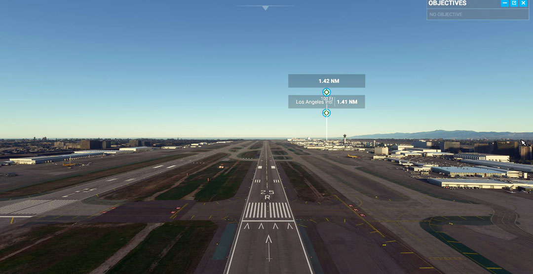
Los Angeles International airport (LAX) is one of the handcrafted airports. Here we are approaching on runway 25 right.

Overflying LAX gives us this view. The handcrafted airports
contain every detail. Not only is each building made just like
the original, but there are
service trucks, trucks delivering in-flight food (who gets that
anymore?), fueling trucks, etc. driving around and attending to
aircraft. When a plane is ready
to depart, the push-back tug hooks up and pushes them out to where they can continue on their own..
Conclusion:
This has been a fun project, occupying much more of my
Covid-at-home
time than I expected, and ending up with a much more elaborate
simulator than I ever planned! I am very pleased with the results
and using the small amount of flight time I have put in during the
build process as a measure, I can anticipate many more hours of pure
enjoyment along with periods of high frustration. I really seem to
have
lost some of my flying skills by not doing any flying for the last 43.5
years! I cannot understand that! My last logbook entry was
December 1976.
As far as the Microsoft Flight Simulator is concerned, it is an
incredible product. Its scenery alone is worth the price of
admission, but the shortcomings, such as support for only one
monitor, prevent it from becoming my main simulator. This
may or may not change with time!
It's time to go flying!
Go to part 2 to see the latest additions and modifications to my flight simulator: