Addendum of 10/25/2020 - Head Tracking:
I have recently been reading about a device called TrackIR along with descriptions of many look-alike devices. In operation, these track the position of the user's head and adjust the view on the screen to show where he is looking. If you look to the right, you see what is to your right, you can look down from looking out the windshield to see the instrument panel, then look right back up to the outside. You can also scoot up in your seat to see over the engine cowl better, etc. This adds a great deal of realism to a flight simulator or an action game, and greatly reduces the dependency on a large view from multiple monitors.
These devices use a special or a modified standard camera above the monitor and a bracket holding 3 infrared emitting LEDs attached to the user's head using a head strap, headphones or a cap. The LEDs are located so that the image the camera receives can be interpreted by software to indicate the position of the user's head in 6 axes: These include:
yaw (left and right angle),
pitch (up and down angle),
roll (tilting the head right and left),
X (moving the head left and right),
Y (moving the head up and down), and
Z (moving the head forward and backward).
TrackIR has been around for a number of years and has been very well received. Really the only complaint, which seems pretty much universal, is that it costs way too much. A complete setup including the IR clip holding the LED's is about $170 to $200. A version only using reflectors on a baseball cap is somewhat less, but the general opinion is that for the best sensitivity and reliability, the LED's are needed. There are many, many Youtube videos describing how to build an equivalent unit for much less, some tout that $20 will buy everything needed. There are also small companies who are selling complete kits of parts to build these units for about $50 to $70.
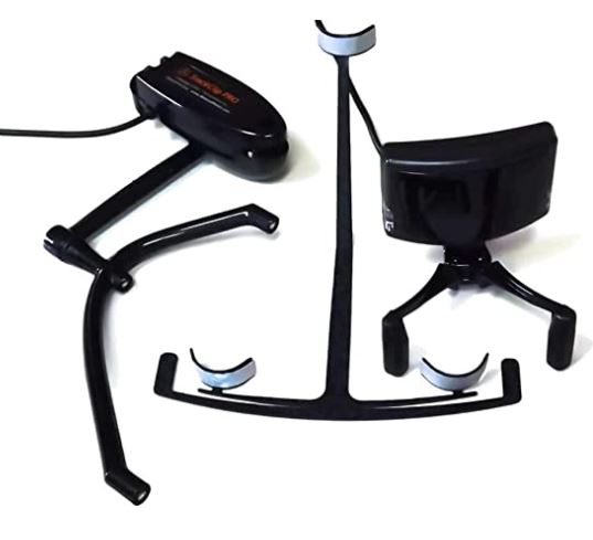
These are some of the head tracking systems currently on the market. The left is the original TrackIR at $200 which includes a reflector for a baseball cap as well as the IR clip. The
center is the Delanclip for 44 British pounds (~$57), and the right is the Track Hat for 45 British pounds (~$58). The latter two require shipping from England.
Reading all these descriptions and seeing many of the Youtube videos got me very interested and I decided to build one and try it out!
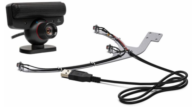
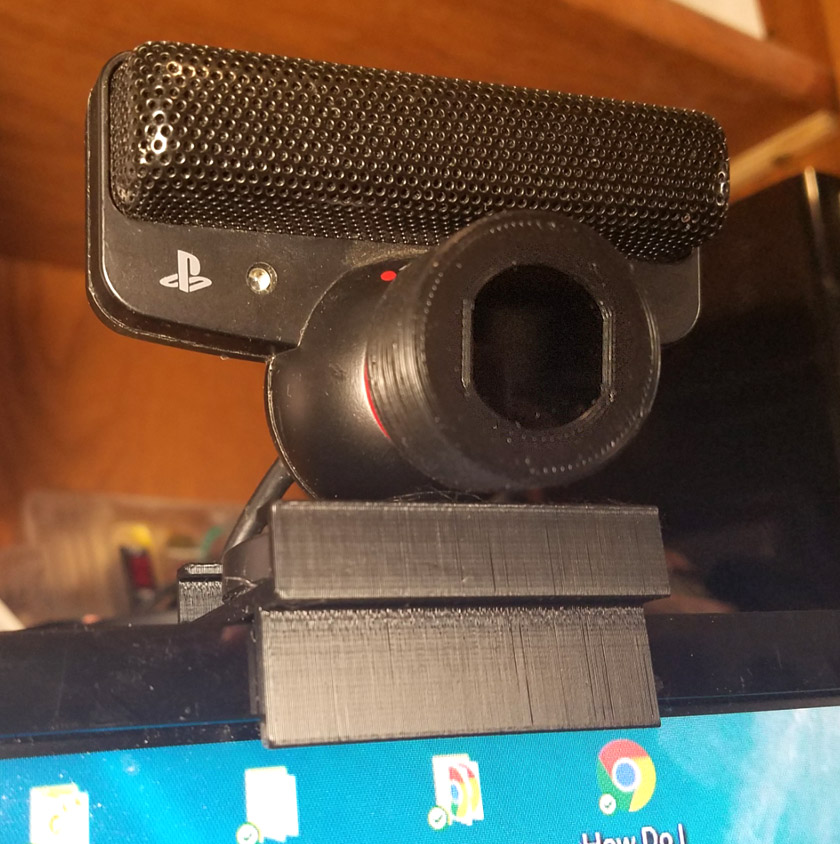
One of the common aspects of virtually all the DIY versions of head tracking is they all seem to recommend the Play Station 3 Eye Camera. This is a very low cost camera that as of several years ago when many of the videos were made, cost only about $5 used. It was selected due to its high refresh rate, its low cost, and the ease of modifying it to block regular light and allow infrared in. The lower resolution, compared to most webcams, is not really a factor in this application. A number of the videos also recommended a specific part number of LED to use. They warned that the cheap, bulk packed IR LEDs were not suitable. Of course I had a selection of these bulk LEDs so I started using the ones I have.
Actually, once I figured out what they were doing, I realized there were only 2 pieces of hardware needed, plus a couple free software packages. The camera along with its modification, and the clip holding the 3 LEDs were all the physical parts I needed, and the software was a driver package to allow the PS3 Eye camera to be recognized by Windows, and a package called OpenTrack to do the translating of the 3 LED dot positions on the camera into the form needed by the games and simulators to change the views accordingly.
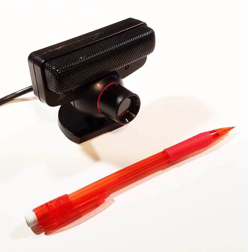
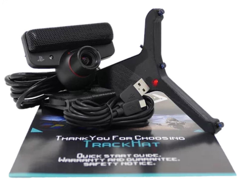
These are the parts I built or modified: The 3D printed head band and LED clip are on the left, and the modified PS3 Eye camera on the right. It's small size is shown by the pencil.
My total cost was $12 for the camera. Everything else I already had. I did spend an additional $16 on the special LEDs which I would use in a new build, but will not exchange
for what I already have, and an optical IR blocking filter I plan to compare to the floppy disk filter currently used.
The LED clip: The first item I tackled was getting some LEDs powered up to see how well they showed up on my existing webcam. Even though that camera has a filter to block IR, enough passed that I was able to get good images. I then covered the lens with a piece cut from a floppy disk, recommended as a poor man's IR pass filter. Although this blocks pretty much all visible light, the IR beams showed through. Concept verified!
Next, I ordered a PS3 Eye camera from Ebay. Prices have gone up since 2017 where they were readily available for $2 to $5. Now they seem to start at about $12 and go up from there with new ones at about $40. Mine was $12. I also ordered some of the suggested part number LEDs from Ebay, and an IR pass filter from Ebay to replace the floppy disk filter. It has to be better! It will look very silly on my tiny camera as the 67mm diameter is almost as tall as the camera. I will print an adapter, and it should work fine, even if it is far larger than required. Maybe I can cut it. I can find smaller filters, but they run over $100 or are shipped from China. Mine was $7 from Edison, NJ.
I then did a little more experimenting with the LEDs. I found I had two different wavelengths of IR LEDs in my drawer, 850 nanometer and 940 nm. I tried each, and the 850s were significantly brighter so I chose them. I then did some testing for beam angle. The signal (brightness on the screen) dropped off pretty quickly as I turned them. They might have been OK, as in practice I will not need to turn my head very far to move the view all the way. Even though the scene I want to look at may be 90 degrees or more to the side, I cannot require my head to turn nearly that much as I still need to be able to see the fixed monitor. I tried sanding the end of the lights to help diffuse the beam with good results. I then found that if I sanded the rounded end pretty much off, leaving a flat, diffuse end, that I could turn it a large angle with little drop off of light. This is the method I chose. I think the narrow beam is probably why people advised against using these parts. I plan to repeat these tests on the recommended parts when I receive them, but may well just relegate them to my parts bin.
Added a few days later: The new LED's arrived. When I tested one against the ones I have used, they had almost identical fields of view - about 160 degrees overall (80 degrees each side), compared to the original unmodified ones at 20 to 30 degrees overall. The new ones can withstand a higher current for higher output, but at the same current they behave almost identically. I will continue with the existing ones, but if I had to do it again, I would use the new ones since no modifications would be needed, and if desired, I could use higher current. Also, they are prettier!
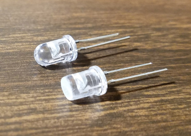
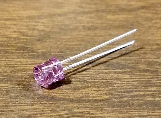
The left shows the LED's I used, the original and the one that had most of the spherical end sanded flat. The flat
rough end diffuses the light and makes it visible over a wide angle. The right shows the new LED as recommended by others.
One of the Youtube videos I watched referenced the 3D printer files for an LED clip on Thingiverse. I would like to thank user sorcerereric for the design. I printed it without modification and it was exactly what I wanted. It consists of two mirror image pieces with bars extending for each LED. Printed rectangular bands hold the two halves together at each LED, and the base is fastened with a pair of zip ties. There are also optional closed-end bands to be used as diffusers, when printed in white, of course. I didn't try these. The arms are hollowed out for wiring and the ends have retaining grooves to securely hold the LEDs in place. Wiring was straight forward with each LED in series with a current limiting resistor, and then wired in parallel. I chose the resistor to provide about 50 milliamps to the LEDs which have a max rating of 60 ma. I then printed a flat plate with a raised boss and a 1/4-20 threaded hole. Yes, the threads printed beautifully and fit the screw with a slightly tight fit.
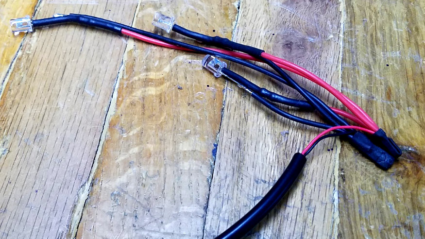
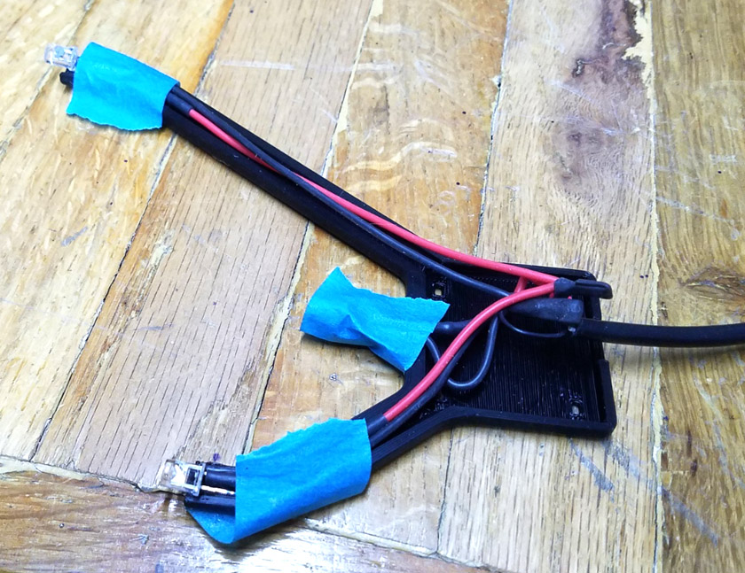
The left shows my completed wiring harness. This is designed to lay in one half of the printed clip. I was not able to hold it all in place to assemble the other half,
so I taped the LEDs into place and ended up laying a strip of tape over the wires. Once loosely assembled, I was able to pull the tape out.
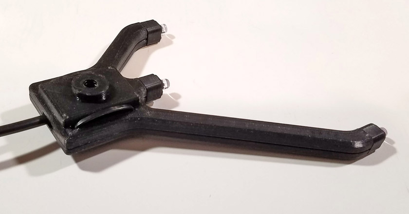
This is the completed LED clip. The plastic bands fit snuggly over the LED areas and clamp them tightly.
Zip ties hold the wiring box together and a super glued plate and threaded hole provide a means of mounting.
The cable is the end of a sacrificed USB cable and plugs into a computer or 5 volt charging plug.
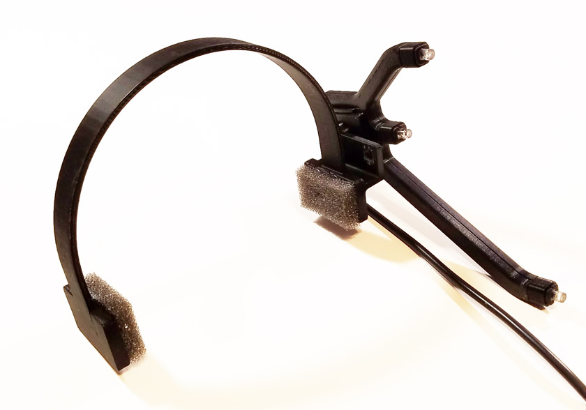
I initially mounted the clip to a fabric headband designed to mount a GoPro camera. It worked OK, but I hated digging through the various bands to align it right to put on. I then printed a simple plastic band, similar to a headphone band, and mounted the clip on that as shown above. I have yet to find out if that is comfortable and stable over an extended time. Note from later: It seems stable and was almost unnoticeable on my head.
The Camera modifications: There were two mods needed for the camera:
1. remove the filter that passes
visible light but blocks infrared, and
2. add a filter that passes infrared but blocks visible light.
The first one is straight forward, but
difficult. To access the existing IR blocking filter on the rear
of the lens, the rear of
the camera needs to be removed. A few screws and some tight clips
eventually allow this. Next the circuit board needs to be removed
by removing a few screws. Then the lens assembly is removed from
the circuit board with 2 screws. On the rear of this lens
assembly is a
small (about 1/4 inch in diameter) glass filter. That is the IR
blocking filter which needs to be removed.2. add a filter that passes infrared but blocks visible light.
The method shown by most of the videos is to carefully carve away or displace the plastic around the lens using a sharp hobby knife. This can take a fairly long time and a LOT of patience, which I don't have. One ingenious fellow used the metal pocket clip from a pen, and repeatedly heated the tube end of it pressing it around the lens melting the plastic. After a number of these heat and press cycles, the lens and some surrounding plastic came out. It was messy, but it worked! The fellow in the video I link below actually has a knife based system that he skillfully works fairly quickly.
Having a machine shop, I used a different approach: After trying enough strokes with an Xacto knife to decide that was not how I wanted to go, I went with my original idea to use my lathe and cut the lens out. I found a tool in my assortment which was already ground to a very thin edge of about .040 inch. I did some additional grinding to assure adequate clearance and set it up. I wrapped a couple turns of masking tape around the end of the slightly tapered lens housing and clamped it in the chuck. It held quite steady and was almost perfectly centered around the filter. I slowly cut a groove almost touching the filter until the filter turned somewhat sideways. I took it to the bench and figured that the filter would fall out with a slight touch. I was wrong! When I hooked the edge of the filter and tried to pull it out, instead of dropping, it shot out toward the rear of my bench like a released spring. I searched, but so far have failed to find it, but still the mission was accomplished. I don't need the filter, but was interested in putting it in front of an IR LED and seeing how much it actually dimmed the image. The end result was that the filter was removed and the body around it was clean and undisturbed. It was an excellent and easy way to remove the filter.
The second mod is straight forward and not difficult. The current IR pass filter I am using is a circle I cut from the thin magnetic disk of a floppy. I popped it into the front of the lens, where it is staying just fine. If I had planned on using the floppy as the permanent filter, I would have cut a square to fit the bottom of the lens and it would have been captive once the lens was screwed back to the circuit board. Other options would be to use a short length of videotape, several layers of exposed developed photography film, or an IR passing optical filter.
I am sorry that I failed to take any pictures while I did the removal of the filter, but there are many Youtube videos showing the whole process (using a knife instead of a lathe) in detail. I have supplied a link below to one of the better ones showing the removal of the filter. Here are a couple images from that video (with permission) showing the lens assembly with the filter and with it removed:
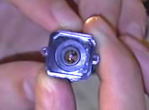
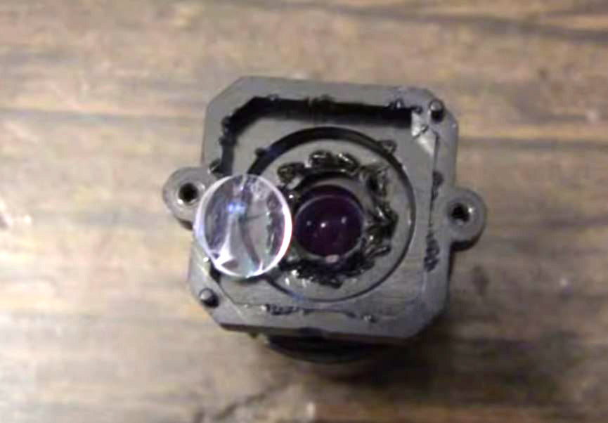
The left shows the rear of the lens assembly with the IR filter still in place. The right shows it after removal. The lathe left the hole clean and smooth.
This is the link to the 9:45 long video:
https://www.youtube.com/watch?v=7jJfuP7YgPA
It is entitled "Playstation 3 Eye Camera - Removing IR Blocking Filter" by Peau Productions. It is part 1 of 2 videos, but shows the complete camera disassembly and removal of the filter. The actual removal of the filter starts at about 5:40 in the video.
Thank you Peau Productions for the excellent video and for the use of the above pictures!
In watching quite a few videos on the subject, only a couple addressed a problem with removing the IR filter, and one of them was wrong! After removing the filter, the focus of the camera is changed. For the camera which showed a reasonably sharp focus from a foot or so and beyond, the focus was now at about 6 inches after removing the filter. Anything farther away was quite blurry. The first video I saw that mentioned a focus shift, recommended placing 2 of the small rubber pads that originally covered screw heads on the back of the camera, between the lens and the circuit board. His logic was that you could then adjust the mounting screws and squeeze the rubber, moving the lens until the focus was good. Unfortunately, that could only move the lens the wrong way!
To correctly adjust the focus, as was properly pointed out in a couple other videos, you need to sand a little plastic from the back of the lens housing, moving the lens closer to the camera sensor! I sanded about 0.004 inch and the focus looked quite good. It only took maybe 20 good strokes on a sheet of fine sandpaper on a flat surface to do. I kept checking the thickness at each corner to keep it even.
Fortunately, even the "wrong way" probably did not harm the results that much. The analyzing software appears to find the center of each dot and use that value for the calculations. This means that even a fuzzy dot will have very close to the same center as a sharp one, and ultimately only lose a small amount of accuracy or stability. I still want that sharper image!
Once the camera was back together and working, I ran the OpenTrack program. This is where you can set all the parameters of the video such as gain, brightness and contrast to make sure no ambient images come through and that the IR spots are bright and clear. The main screen of the program shows a small screen image of the received dots. There is also a picture of a pink octopus which moves and twists as you move your head. The program also provides graphs that you can set to define exactly how you want the output to behave for certain head movements. It is a wonderful open source program, not elaborate, but functional
.
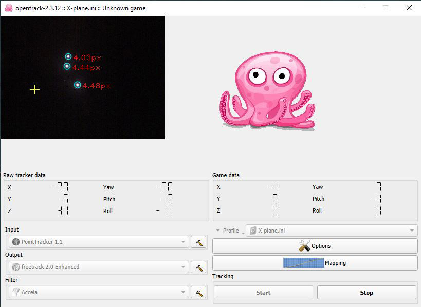
This is the main screen of Opentrack. The small video screen shows an ideal totally black background with clearly defined images of the IR LEDs. As long as
each dot has the blue circle, the program is able to use it. The pink octopus moves and twists as you move your head. The numbers half way down indicate the
position as sensed and the resultant output to your program after scaling. Other options can be selected at the bottom, including the mapping which brings up six
pairs of large graphs where you define exactly what you want sent to your program for each head position.
Addition of 11/3/2020:
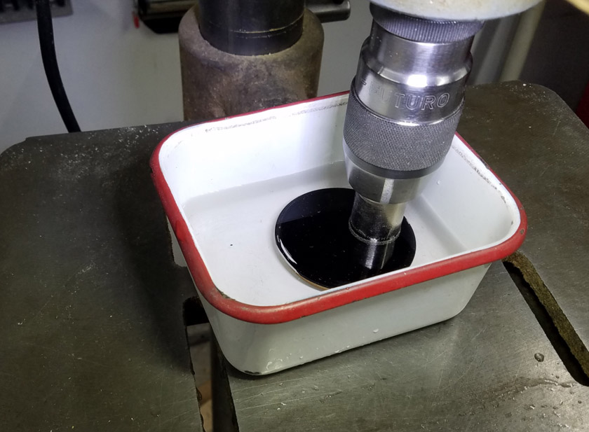
The IR pass filter arrived a short time ago and I had to decide how to implement it. At 67mm diameter, it would dwarf the camera by the time I mounted it in front of the lens. I browsed some Youtube videos (imagine that!), and ran across one which talked about drilling holes in glass. Among several options was a diamond grit covered hole saw, which seemed to effortlessly cut round holes in glass, with the byproduct of leaving the round piece of glass cut from the hole intact. Ebay had a set of 15 different sizes of these diamond hole saws for about $12 so I ordered them. When the saws arrived I searched for a scrap of glass to test one of them on, and discovered that I had discarded all the glass I had in Escondido before moving here,and I had none. I realized I could easily fit 3 holes the size I need into the large filter. They warn you to keep the cut wet at all times, so I machined a piece of MDF to fit within the frame of the filter and totally support the glass itself. I then put this in a small tray and covered the pieces with water. I had no idea the glass of the filter was as thin or fragile as it was, a little over 1/32 of an inch, until the first piece I cut shattered. I then tried a second cut, trying to feed the diamond saw very slowly, and that piece also broke, but not as badly as the first. I then tried my final possible cut using an extremely light touch and making sure I kept cutting until I was sure I was all the way through. At first I thought I was successful, but when the piece came out of the saw, it had two edges missing. One was a straight line and the other was like a gouge. The good part was that the glass that was intact was wide enough that I thought I could make it work. In the end, I did!
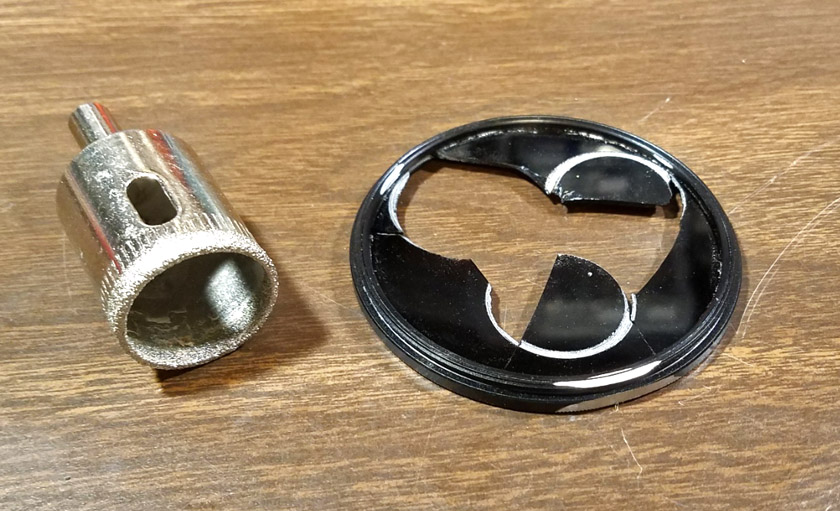
The left show the cutting operation, running the spindle at a very slow speed. There is a round piece of MDF under the filter providing full support for
the glass. The right shows the diamond encrusted hole saw and the final sad remains of the filter. The "successful" third try has only a small part
missing on one side, and a small irregular piece on the other. What was left was adequate for my final filter.
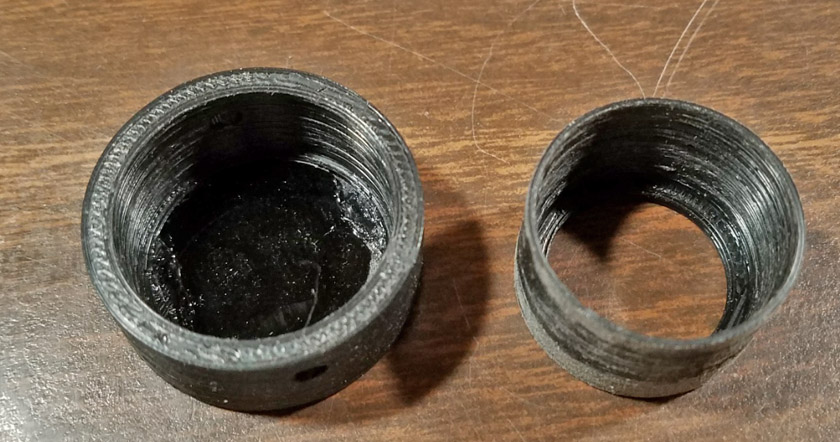
The filter is glued into the outer piece of the filter holder. The glue, seen on the left and right sides, was
applied where the filter was missing its edges. The filter had not been cleaned at this point. After cleaning,
the inner piece on the right was pressed into the outer part, tight against the filter.
As an aside, since the 15 diamond encrusted hole saws came jumbled in a plastic bag, I designed and printed
a plastic holding case for them. It should be easy to find the one I want in the future.
And here is the installed filter. The holder has a tapered inside which
fits tightly over the tapered camera lens. The flat sides of the opening
were required to allow the imperfect filter to totally cover the opening.
The net result of replacing the floppy disk filter with a true optical infrared pass filter was good. I am sure that it is better than the floppy material, but in the end it is really hard to tell the difference. The adjustments of gain and exposure are quite different for the two filters, and if the settings are made to show a normal type detailed photograph as lit with infrared, the new filter is far superior, actually the only one that really works. When the settings are dialed to totally eliminate all detail except for the 3 bright spots from the IR LEDs, each filter seems to do the job just fine!
Results of the head tracking:
I have now flown both Microsoft FS 2020 and X-Plane 11 using this head tracking system. It is truly amazing! Initially there were some weird effects, such as looking to the side, and suddenly having the view snap to looking straight back. After adjusting the mapping, which determines how far the view moves relative to the head movement, that was much better. I got everything pretty well tuned for MSFS, and flying it was really great. Even though there is only one monitor, it was quite intuitive to just glance to the right side and the view shifts to show the view to the right. The same is true for up and down, easily seeing the instruments by just looking down, then back up to see out again. If you cannot see all you would like over the engine, you sit up a little higher and your view is from a higher point. I did find that disabling the roll axis (head tilt left and right) improved things. Randomly tilting the view left or right did nothing for clarity and was just generally annoying and confusing. The other 5 axes are all beneficial.
After getting it pretty well tuned for MSFS, I tried X-plane. In this program I had to find a check box to enable head tracking, but then it all worked. The tuning was definitely not the same: it was much more sensitive. I could easily move my head to the left, and essentially poke my head out the side window. I could also raise my head right through the roof and look over the top of airplane. The other thing I noticed was that if I moved closer to the instrument panel to see the instruments more easily, the effect was greatly multiplied. A slight shift filled the screen with the panel, and a slight shift back put me in the back seat. Some simple tuning corrected all these problems and flying was again smooth and natural.
The tracking software fortunately offers the option of multiple profiles, allowing me to precisely tune it for each simulator separately, then to just select the correct profile when starting a flying session.
I found it amazing how easily I adapted to just looking where I wanted to see, and how sorely I missed it when I turned head tracking off. I did have one minor problem: I would occasionally look up or down when I really wanted the plane to fly up or down, and similar effects of trying to cross control. This was less of a problem as I got a little more experience with the system and doesn't look like a long term problem. Just one of my coordination!
I feel this was a very easy improvement to build and implement which has yielded an amazing improvement in convenience and the overall immersion in the flying experience. However, I find that the complexity of the setup, wearing and aligning the LED headband, connecting the power and data cables, opening the additional programs, etc. puts me off. Therefore I am mostly not using it and just start flying without it.
I replace my quadrant assembly! May 2022:
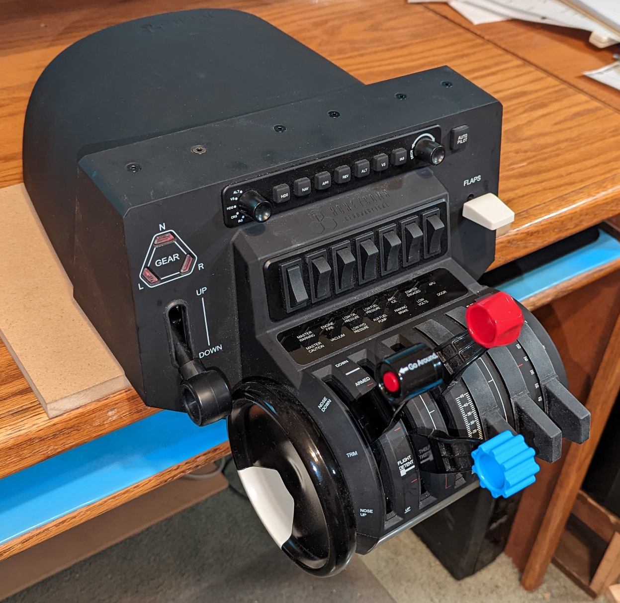
I thoroughly enjoyed designing and building my quadrant assembly, and it served me well for about 2 years. It also was a wonderful learning tool, but all good things must come to an end. Ever since I started building my throttle quadrant, I have been lusting over an early announcement photo and subsequent information about a quadrant assembly to be built by Honeycomb, the maker of my yoke. I figured that if the product matches its early publicity photos, it would be wonderful! It is a beautifully built system which design-wise matches my yoke and includes everything I designed into my own quadrant and then some. Ever since the announcement in early 2020 I have kept my eye on their progress with a number of early reviews and write-ups about it. Unfortunately, coming out right at the start of the Covid pandemic, nothing arrived on time, and the official release date kept being extended. The few units that found their way into stores were scooped up immediately and there just was no availability. In May of 2022, after being patient for about two years, I saw an ad on the Xplane site offering the quadrant at a discounted price, and claimed to have them in stock. I figured "if not now, then when?" (as I steadily add years to my age, I find myself asking this a lot!). A few days later it arrived and was everything that it appeared to be. As much as I am proud of the one I designed and built, this one is certainly better, matches my yoke (which I also love), and has the same very handy mounting plate system as the yoke.
It came with 6 engine control lever positions and a number of individual levers which can be slid onto stubs at each position to form controls for just about any airplane, from a Piper Cub to a 747! The control "stubs" even have electrical contacts and some of the levers have a push button or extra lever on them which are functional. It is truly a masterpiece of engineering! It has the complete auto-pilot control panel, a trim wheel, a number of toggle switches, gear status lights, and 14 miscellaneous status lights. It also has adjustable friction on the control levers. I have no regrets about my purchase!
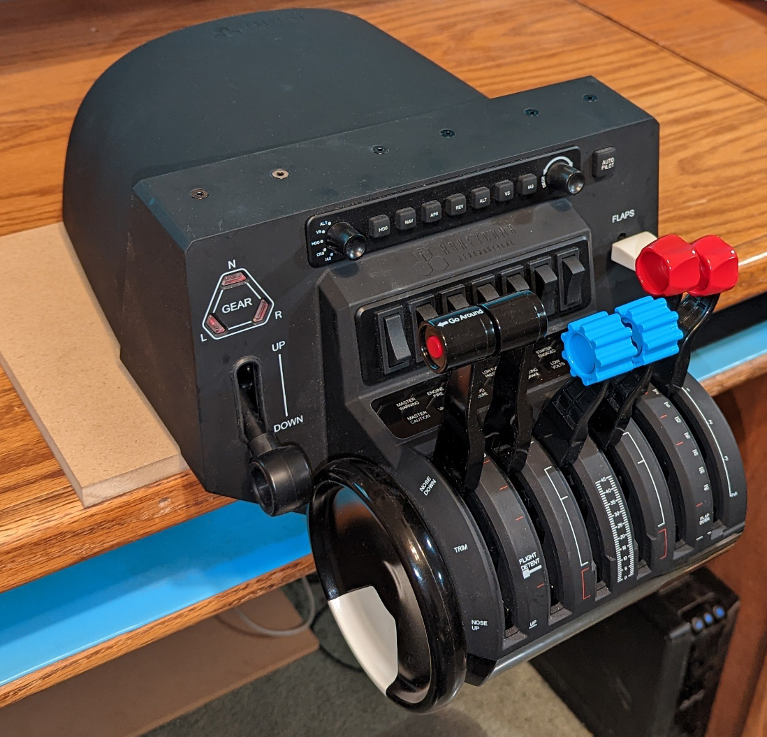
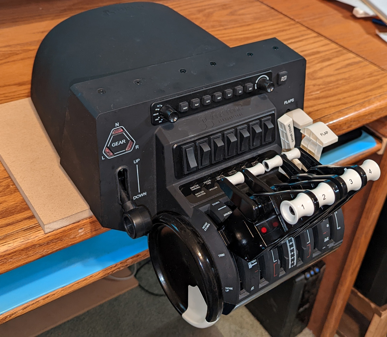
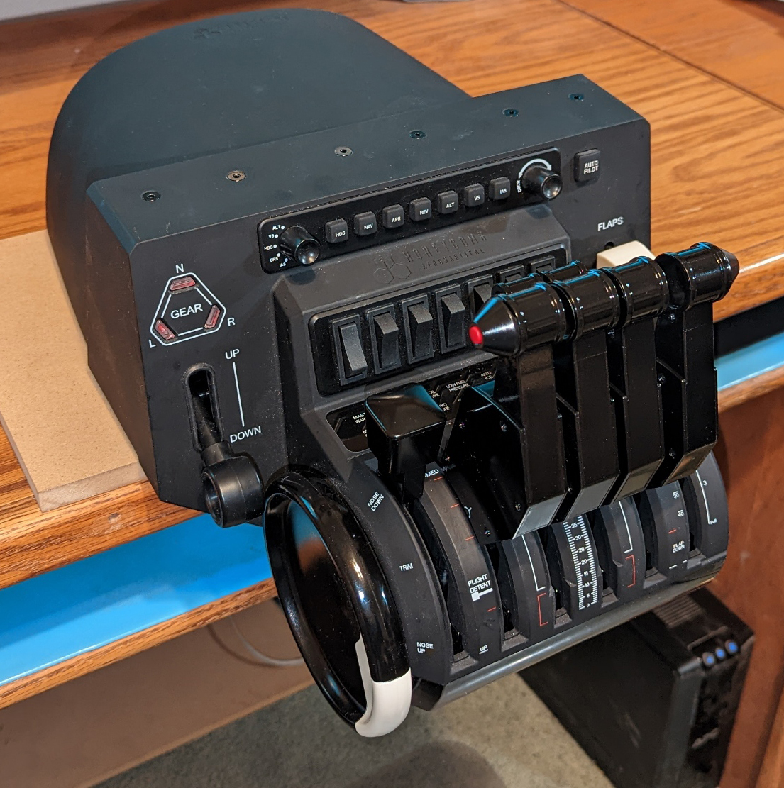
The various control levers can be arranged in many ways to fit the appropriate aircraft. The two left hand pictures show single engine and twin engine light aircraft. The two on the right are jet airliner configurations.
They are shown for 4 engine jets using all the levers. For fewer engines, fewer levers are used.
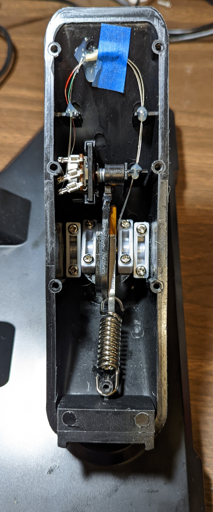
I have never particularly cared for the CH rudder pedals I bought from Ebay. They are far too close together and have a plastic feeling as you use them. The Saitek pedals have always been listed at or near the top for reasonably priced pedals, but at $180 I did not feel they were worth it to me. One day I spotted a Craigslist ad for a set for $50! After assuring me he would hold them for a few hours for me to get down to Cave Creek (about 1 1/2 hour drive each way), I met with him and bought them. There was a broken spring holder on one side, but I had seen Youtube videos and knew it was a minor problem.
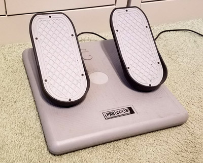
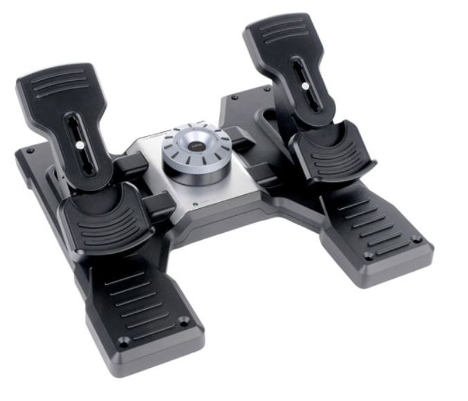
The CH pedals I have replaced are on the left, and as I seem to have never taken a photo of my Saitek rudder pedals prior to modifying them, here is a
picture from an ad on the internet.
As with most of my other used purchases for this simulator, it required an immediate repair, but I seem to be pretty good at these repairs. A known weak spot of these pedals, and the main thing that keeps them from being rated even higher is a tendency for a molded plastic part to break where it holds one end of the toe brake spring. One of these was already broken. After a couple hours designing and milling a couple small pieces from aluminum, the pedals were back together and should never lose the spring support again.
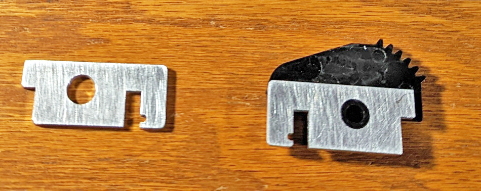
The aluminum parts have a much stronger hook for the springs than the plastic part under it did. The installed part is shown on the right.
As you press the top of the part to apply the toe brakes, it tilts, pulling the spring with a lot of force, and the stationary gear teeth rotate the potentiometer
as it moves past, sending the braking signal to the simulator.
These pedals work very well. They are much wider than the CH pedals and feel much like a real plane's pedals. Another advantage of these pedals is the adjustable "fluid damping" or tension control. This allows you to control the force required to move the pedals to get the feel of a specific airplane.
I don't much care for the design of the "foot holders" on the pedals of either the CH or the Saitek, where you place you whole foot on the pedal and have a heel stop. This is not the way most airplane pedals are made, and after using them for a few months decided to adapt them to Cessna type pedals. Several examples are listed on Thingaverse. I chose a pedal design which was based on the pedals in Cessna 172 planes. The author* added a base to adapt them to the Saitek pedal assembly. I downloaded the print files for these, but in typical fashion wanted to change them. I ended up using their basic design, but totally redrawing them in my CAD program so I could readily edit the details. Primarily I split them into two parts for each side, a base unit and a pedal. I also changed the visual design to mimic the actual Cessna pedals more closely. I am now much happier as I think they allow for more precise control, are more comfortable to the feet, and are more realistic. Besides, they just look cool!
*Thank you to allanglen who designed the original Cessna pedals to be used with MFG Crosswinds pedals and to jladd3 who adapted the design for use on the Saitek pedal assembly! I owe you both!
I particularly like the feel of the pedal assembly now that it has the Cessna type pedals, shown here ready to fly.
By separating the base and the pedal into 2 discrete pieces, I eliminate having to use supports during printing, I can use all 6 screws to
attach the base to the toe brake housing, and if I decide I want to change some detail in the pedals, I only have to replace the pedal half.
Making an encoder box
Air Manager has recently added a very useful option to their already superb program: support for using an Arduino controller. With very little effort, you can connect a button, a switch, a potentiometer, or an encoder (and probably a number of other input devices) to pins on the Arduino. Then after flashing the program into the Arduino (one time) using a single click in Air Manager you open a small routine for that input, tell it what pins you connected to and check a box or two to describe the action you would like to see and you are done. Now when Xplane and Air Manager are running, these new devices will set or activate the plane's controls, switches, instruments, etc. as you specified. If there is no defined routine already tailored to the specific device, a few lines of a simple programming code will create it.
GREAT NEWS! A couple weeks ago, SimInnovations (maker of Air Manager) released an Arduino plug-in for Microsoft Flight Simulator 2020, so now this box is usable with both the simulators I fly
This box provides a marvelous tool for adding dedicated controls to perform specific functions. For example you could define a knob (encoder) to always adjust the autopilot heading bug on the directional gyro by turning it, or setting it to the current heading by pressing it. Then you could select another one to set the heading on the primary OBS (Onmi Bearing Selector which selects a path for navigation), and a third to do the same for the secondary OBS. Switches can be set to control lights or electronics, and just about all the tasks in the cockpit.
To take advantage of this new capability, I initially designed a box to hold an Arduino, two dual encoders such as for tuning radios, two single encoders for simple knob turning, and 4 push buttons for any tasks requiring a brief signal.
I chose an Arduino Mega 2560, which has far more inputs than any other of the supported Arduino models and I provided mounting for the 8 devices above. I quickly found that I needed more encoders and fewer push buttons, so I re-designed the front half of the case to mount 2 dual encoders and 6 single encoders. As long as I connect the Arduino to the computer running Air Manager and Xplane using a USB cable, the controls will work.
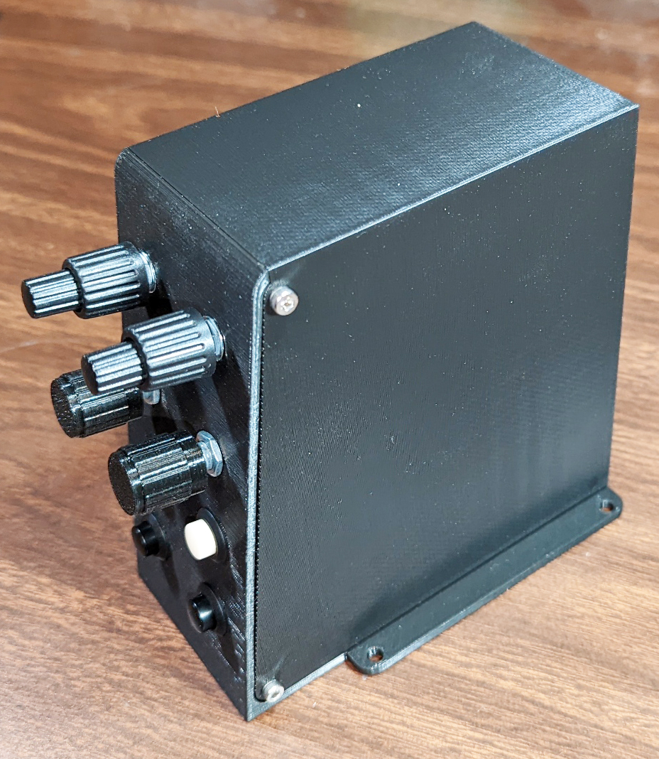
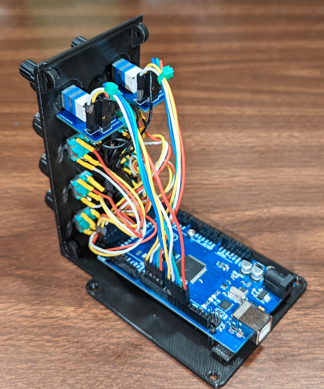
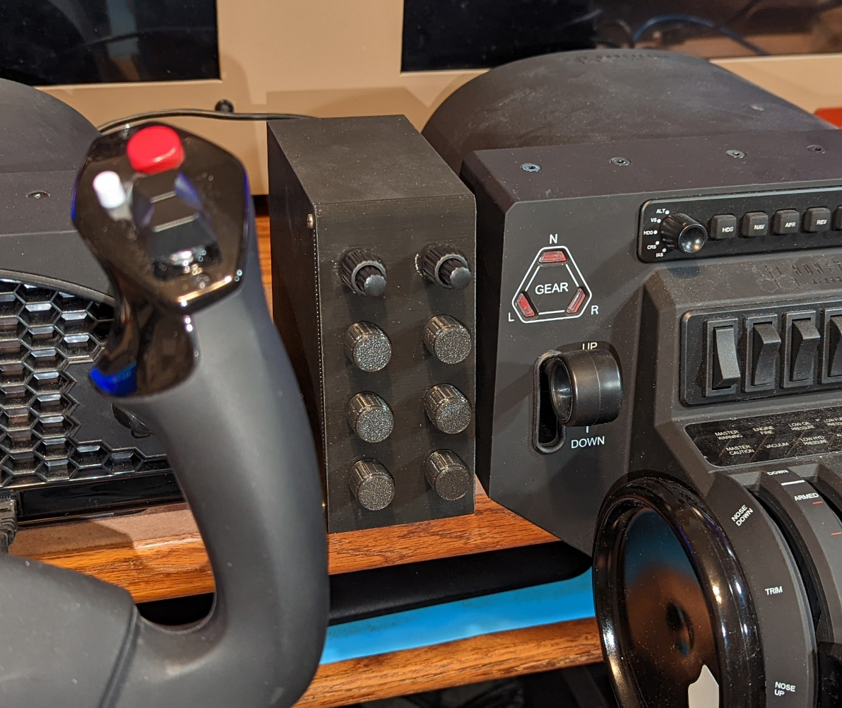
On the left is the original 4 encoder, 4 push button version of the box. The other two pictures show the wiring of the 8 encoder box and that box mounted between the yoke and the quadrant.
Monitor extension tables:
My initial 3 monitor setup was using three 27 inch monitors which sat on the rear of my desk, and where the right hand monitor hung over the end of the desk, I propped it up on my computer case. This worked, but was pretty wonky. Then one of my monitors failed and I replaced it with an extra wide 34 inch monitor, and then later still I added a 2nd identical monitor to replace the remaining 27 inch ones. To better accommodate these monitors and to relieve clutter, I redesigned my desk layout by removing the hutch on the rear and adding shelves on the wall behind it. The lowest of these shelves became my monitor support. The new monitors are the same height as a 27, but almost half again as wide.
Now when I fly my simulator, even though I have about the same total screen height and width, having the bezels in the very center of my flight path is extremely annoying. I found that I could separate the two wide screens and put one of my old 27 inch monitors in the center. This worked very well, except now the two wide monitors hung off both the end of the shelf and the front. I initially proved the concept with boxes and boards on my desk to hold the overhanging monitor feet. I needed something to add table area in specific areas that could be easily adjustable to be level with the shelf and be portable.
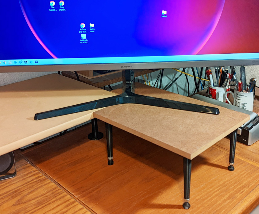
The extensions are made of 1/2 inch MDF with 3D printed legs attached.
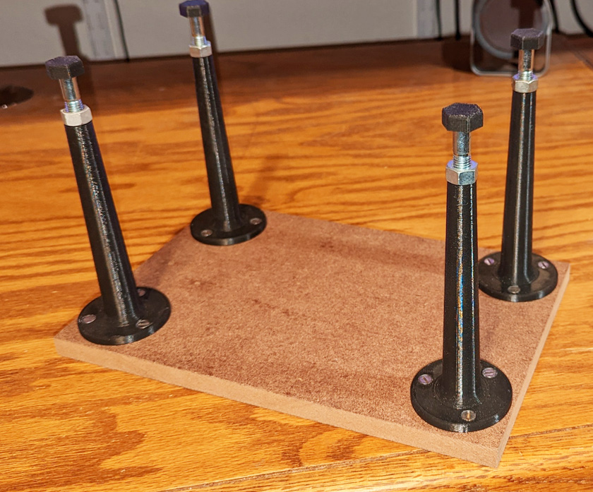
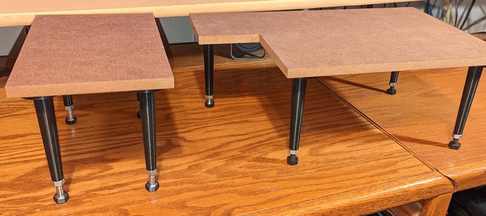
The legs are hollow with the end threaded for 5/16 bolts. A finger tight lock nut and printed caps over the bolt heads give the
ability to easily level the tables and provide a non-scratch contact with the desk. They are light weight and stack for storage.
I Go VR! October 2022
I have now rendered much of my prior work on the simulator obsolete!
I bought a Virtual Reality (VR) headset! Using this headset, I no longer need multiple monitors, the table extensions for them, an auxiliary instrument panel, or some of the smaller items I have made for my simulator. The headset provides a pair of high resolution displays, a pair of small speakers just off my ears, and a pair of microphones (I haven't tried these out yet). In use it provides a stereoscopic image which shifts precisely as you move your head (think really good head tracking) so when you turn your head you see exactly what you would expect to see at that position. The speakers also provide excellent sound to go along with the visuals. The results are stunning! It feels like you are actually flying and you can see anything you want just by looking. No need to click the hat switch to change your view.
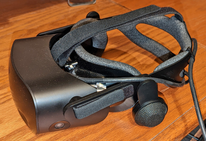
This is my VR headset, known formally as the HP Reverb G2 rev 2. It is listed by most reviewers on Youtube as the best choice of an affordable (less than about $600) VR headset for use with
flight simulators. There are complaints that the head and 3d remote tracking is too slow for some of the "quick draw and shoot them down" games
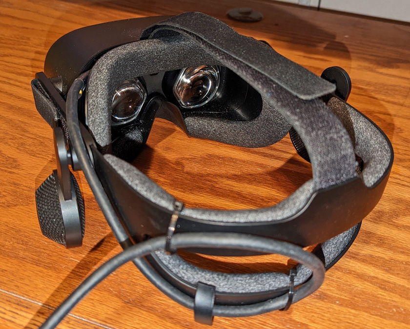
The displays have a resolution of 2160 by 2160 pixels in each eye, excellent speakers which remain about 10mm (0.4 in) away from the ear, and two microphones. It has a 6 meter (about 20 ft) cable, which
is much longer than I need, but is for the scenarios where you are up walking through your virtual world. This headset uses inside-out head tracking. There are 4 cameras built into the outside of the headset
which can see items around it. Calculating the movements within each camera allows the unit to determine just what movements you are making in 6 axes (pitch, roll, yaw, up-down, forward-back, and left-right).
I was quite concerned initially about the complexity of setting it up and getting it working. I had been reading about needing the program STEAM to run it, then I would read that you also need STEAM for MIXED REALITY and WINDOWS MIXED REALITY. Wow, I 'm going to have to track these programs down and learn how to start and use them with my headset. It was a piece of cake! I easily found the programs and installed them. I then plugged in all the cables from the headset. It connects to a Display Port on the graphics card, a USB C port (they supply an adapter to type A), the supplied power supply to a junction box on the cable to the headset, and an AC plug-in for power. I connected all these and my 3 extra programs automatically did their stuff and my headset was alive! I have the power supply plugged into an outlet strip, and can now turn the headset on and off with its switch.
I spent a lot of time playing with the demo program that comes up when I start the headset. It puts you in a cliff house with interesting walls and furniture, and quite a few panels containing further actions. One of these is a 3d work board with a number of images on the board. The first one I clicked was an elephant on a pogo stick. You click on it and he pops out of the board in full 3d, and is suspended in space in front of you. You click him again and get a brief sign "loading" then he starts hopping on his pogo stick around the floor with a musical background. It really feels like you could reach out and touch him. Other scenes are a Chameleon on a bicycle, same type of thing, except the first time I tried it he biked, in midair, right through me! I turned around and there he was. Probably the most awesome effect was a picture on the wall. Clicking on it releases several butterflies into the room and they just fly around you. Using the hand controllers that came with the headset, you can click a place in the house and yard and immediately be transported to that spot. There is a wall around the patio which is overlooking the sea. I moved to where I was standing right on a corner of that wall. I cannot describe the feeling in my stomach when I looked straight down to the water way below me!
It also works with my flight simulators!
Both Xplane and Microsoft Flight Simulator 2020 (MSFS) have a check box that will allow you to switch the video and audio to the VR headset instead of the monitors. This and plugging in (or turning the outlet strip switch) and you can fly in VR. The effects are truly amazing. I wish there was a way to duplicate the effect in this writeup, but that is just not possible. When you are flying with VR, you feel you are actually in the cockpit flying the plane. Everywhere you look you see just what you would see if really flying. To check your position on downwind, you quickly glance out the side window to see the runway, If an instrument or label on the instrument panel is not clear enough, leaning forward will put you closer so you can read it. If you are looking for something on the ground and the engine cowling is in the way, you sit up higher in your seat and you can see it. You can quickly glance below the instrument panel to check on the trim and flaps, or whatever is down there for the particular plane you are flying. On larger planes with overhead controls, just look up and there they are. The level of immersion is fantastic! Several times I have found myself ready to put something down on the seat next to me before I realized that there is no seat next to me!
There is one major downside to flying VR: You are totally blind to the real world! Using your flight controls, finding the correct switch to change or the button to press all has to be done by feel or muscle memory! With the current technology all you can see is the virtual airplane and the scenery, but not your interaction with it. There are techniques being developed to solve this including hand tracking and mixed reality, but they are not available to the general hobbyist yet. But they are coming!
The goal is to be able to fly without having to break your immersion by using the keyboard or the mouse (or 3D controller from the headset). The most common current methods of interacting with the controls are:
So far, I have been flying using a combination of #2 and #3. I use my mouse to control everything I don't have another way to control. I use the menu to select the several most important knobs using the Knobster, and if I desire and have the correct Air Manager panel set up, I can use the knobs of my encoder box where I can have 2 dedicated dual knob encoders and 6 single knob ones. With these options, I should be in pretty good shape. I have not really tried these very much in actual flight, as I have not yet started to fly taking full advantage of the navigation systems. For just flying around VFR (visual flight rules - good visibility) you seldom need to change any of these (since I have not tried their "talk to the controllers" features yet. As I work out the details and become comfortable with them, I will start some IFR (instrument flight rules - poor to no visibility) flights where I rely strictly on my instruments and navigation equipment.
I am still quite dependent on my mouse, but have pretty much been working without needing the keyboard. I'm half way there!
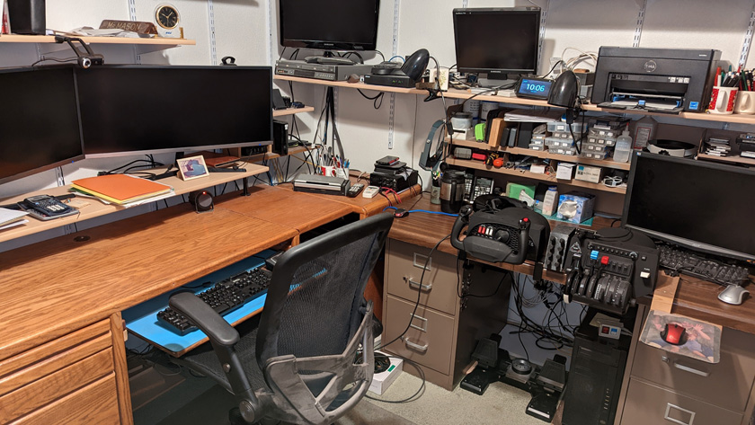
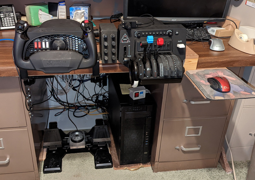
My too-small office is set up with two desks pretending to be a corner desk. Previously my simulator was set up on my main desk in front of the two monitors. This was handy for flying,
but was a real nuisance for normal computer work. Since VR needs no external monitors once started, I decided to move to my other desk. As long as I can set up my controls and my
pedals, I am good and I can leave the system set up as long as I want. The computer at the new setup location is my backup system and has nothing to do with the simulator. I started out
using a TV tray for my mouse, but it blocked a file drawer I need to access frequently, so I built a cantilevered mouse shelf.
A brief summary of my history with flight simulators:
I go way back with flight simulators. I actually started in about 1965, during the period I was an active pilot. Gene (one of my partners in a 1956 Cessna 172) and I heard about a Link Trainer for sale in Santa Monica, CA. and ended up buying it. We hauled it to my garage in Escondido, about a 2 1/2 hour drive, and after some work got it running. Our goal was to set it up in Gene's downstairs basement/rec room, but the Link was too tall to fit. We cut the base down in height and modified the lid to use less height when opening and got it to fit. We added several features to the Link to allow it to use more modern navigation aids than were initially designed in. Then after we both obtained our Instrument Ground Instructor ratings from the FAA, our company, IFR Associates was in business.
Over the course of several years we gave lessons to a variety of local pilots some of whom were working on obtaining their Instrument Ratings, some who wanted to refresh their skills, and others who just wanted to fly the Link for fun. We had one student who went on to become a pilot for Pacific Southwest Airlines which was based in San Diego.
I have now rendered much of my prior work on the simulator obsolete!
I bought a Virtual Reality (VR) headset! Using this headset, I no longer need multiple monitors, the table extensions for them, an auxiliary instrument panel, or some of the smaller items I have made for my simulator. The headset provides a pair of high resolution displays, a pair of small speakers just off my ears, and a pair of microphones (I haven't tried these out yet). In use it provides a stereoscopic image which shifts precisely as you move your head (think really good head tracking) so when you turn your head you see exactly what you would expect to see at that position. The speakers also provide excellent sound to go along with the visuals. The results are stunning! It feels like you are actually flying and you can see anything you want just by looking. No need to click the hat switch to change your view.
This is my VR headset, known formally as the HP Reverb G2 rev 2. It is listed by most reviewers on Youtube as the best choice of an affordable (less than about $600) VR headset for use with
flight simulators. There are complaints that the head and 3d remote tracking is too slow for some of the "quick draw and shoot them down" games
The displays have a resolution of 2160 by 2160 pixels in each eye, excellent speakers which remain about 10mm (0.4 in) away from the ear, and two microphones. It has a 6 meter (about 20 ft) cable, which
is much longer than I need, but is for the scenarios where you are up walking through your virtual world. This headset uses inside-out head tracking. There are 4 cameras built into the outside of the headset
which can see items around it. Calculating the movements within each camera allows the unit to determine just what movements you are making in 6 axes (pitch, roll, yaw, up-down, forward-back, and left-right).
I was quite concerned initially about the complexity of setting it up and getting it working. I had been reading about needing the program STEAM to run it, then I would read that you also need STEAM for MIXED REALITY and WINDOWS MIXED REALITY. Wow, I 'm going to have to track these programs down and learn how to start and use them with my headset. It was a piece of cake! I easily found the programs and installed them. I then plugged in all the cables from the headset. It connects to a Display Port on the graphics card, a USB C port (they supply an adapter to type A), the supplied power supply to a junction box on the cable to the headset, and an AC plug-in for power. I connected all these and my 3 extra programs automatically did their stuff and my headset was alive! I have the power supply plugged into an outlet strip, and can now turn the headset on and off with its switch.
I spent a lot of time playing with the demo program that comes up when I start the headset. It puts you in a cliff house with interesting walls and furniture, and quite a few panels containing further actions. One of these is a 3d work board with a number of images on the board. The first one I clicked was an elephant on a pogo stick. You click on it and he pops out of the board in full 3d, and is suspended in space in front of you. You click him again and get a brief sign "loading" then he starts hopping on his pogo stick around the floor with a musical background. It really feels like you could reach out and touch him. Other scenes are a Chameleon on a bicycle, same type of thing, except the first time I tried it he biked, in midair, right through me! I turned around and there he was. Probably the most awesome effect was a picture on the wall. Clicking on it releases several butterflies into the room and they just fly around you. Using the hand controllers that came with the headset, you can click a place in the house and yard and immediately be transported to that spot. There is a wall around the patio which is overlooking the sea. I moved to where I was standing right on a corner of that wall. I cannot describe the feeling in my stomach when I looked straight down to the water way below me!
It also works with my flight simulators!
Both Xplane and Microsoft Flight Simulator 2020 (MSFS) have a check box that will allow you to switch the video and audio to the VR headset instead of the monitors. This and plugging in (or turning the outlet strip switch) and you can fly in VR. The effects are truly amazing. I wish there was a way to duplicate the effect in this writeup, but that is just not possible. When you are flying with VR, you feel you are actually in the cockpit flying the plane. Everywhere you look you see just what you would see if really flying. To check your position on downwind, you quickly glance out the side window to see the runway, If an instrument or label on the instrument panel is not clear enough, leaning forward will put you closer so you can read it. If you are looking for something on the ground and the engine cowling is in the way, you sit up higher in your seat and you can see it. You can quickly glance below the instrument panel to check on the trim and flaps, or whatever is down there for the particular plane you are flying. On larger planes with overhead controls, just look up and there they are. The level of immersion is fantastic! Several times I have found myself ready to put something down on the seat next to me before I realized that there is no seat next to me!
There is one major downside to flying VR: You are totally blind to the real world! Using your flight controls, finding the correct switch to change or the button to press all has to be done by feel or muscle memory! With the current technology all you can see is the virtual airplane and the scenery, but not your interaction with it. There are techniques being developed to solve this including hand tracking and mixed reality, but they are not available to the general hobbyist yet. But they are coming!
The goal is to be able to fly without having to break your immersion by using the keyboard or the mouse (or 3D controller from the headset). The most common current methods of interacting with the controls are:
- Use the 3d controller to click on a control. Using a "normal" movement click to press a button, swipe up or down to change a switch, or click on a knob and twist your wrist to turn it. This is the hardest to do. Most radios have a dual level knob where you turn the large knob for whole number frequencies, the small knob for the decimal part of the frequency, and press the knob to switch between active and standby frequencies. The areas you need to click to select one of these functions of a knob are very small and hard to hit, and for the turning of the knobs you need to do it repeatedly as your wrist will not turn far enough for most changes and any detents, it is hard to stop exactly where you want. If you miss by a small amount when you click you may have to start over again. This is difficult and frustrating.
- Use a conventional mouse and again click or swipe for the switches and buttons. For the knobs you have to select the correct area and draw a circle around the knob to turn it, or much easier turn the scroll wheel and the knob will turn. You still have the problem of having to click on the correct area.
- Use a Knobster. I talked about the Knobster earlier and installed the DIY version in my instrument panel. SimInnovations has created plug-ins for both Xplane and MSFS that allow use of the Knobster without having to use Air Manager. To differentiate between the standard use of the Knobster and the direct to simulator use, these applications are called KnobXP for Xplane and KnobMS for MSFS. One disadvantage is that the DIY Knobster will not work. You must have the native USB version which only they sell (for about $130). I bought one. It also works differently than the Air Manager application, where you just mouse click or touch a control (on touch screen monitors), then turn the knob on the Knobster. In this application the plug-in generates a small menu of controls which you can select from a large list. You need to click on your desired control on this menu, then your Knobster is linked to that control and you tune as you would in real life.
So far, I have been flying using a combination of #2 and #3. I use my mouse to control everything I don't have another way to control. I use the menu to select the several most important knobs using the Knobster, and if I desire and have the correct Air Manager panel set up, I can use the knobs of my encoder box where I can have 2 dedicated dual knob encoders and 6 single knob ones. With these options, I should be in pretty good shape. I have not really tried these very much in actual flight, as I have not yet started to fly taking full advantage of the navigation systems. For just flying around VFR (visual flight rules - good visibility) you seldom need to change any of these (since I have not tried their "talk to the controllers" features yet. As I work out the details and become comfortable with them, I will start some IFR (instrument flight rules - poor to no visibility) flights where I rely strictly on my instruments and navigation equipment.
I am still quite dependent on my mouse, but have pretty much been working without needing the keyboard. I'm half way there!
My too-small office is set up with two desks pretending to be a corner desk. Previously my simulator was set up on my main desk in front of the two monitors. This was handy for flying,
but was a real nuisance for normal computer work. Since VR needs no external monitors once started, I decided to move to my other desk. As long as I can set up my controls and my
pedals, I am good and I can leave the system set up as long as I want. The computer at the new setup location is my backup system and has nothing to do with the simulator. I started out
using a TV tray for my mouse, but it blocked a file drawer I need to access frequently, so I built a cantilevered mouse shelf.
A brief summary of my history with flight simulators:
I go way back with flight simulators. I actually started in about 1965, during the period I was an active pilot. Gene (one of my partners in a 1956 Cessna 172) and I heard about a Link Trainer for sale in Santa Monica, CA. and ended up buying it. We hauled it to my garage in Escondido, about a 2 1/2 hour drive, and after some work got it running. Our goal was to set it up in Gene's downstairs basement/rec room, but the Link was too tall to fit. We cut the base down in height and modified the lid to use less height when opening and got it to fit. We added several features to the Link to allow it to use more modern navigation aids than were initially designed in. Then after we both obtained our Instrument Ground Instructor ratings from the FAA, our company, IFR Associates was in business.
Over the course of several years we gave lessons to a variety of local pilots some of whom were working on obtaining their Instrument Ratings, some who wanted to refresh their skills, and others who just wanted to fly the Link for fun. We had one student who went on to become a pilot for Pacific Southwest Airlines which was based in San Diego.
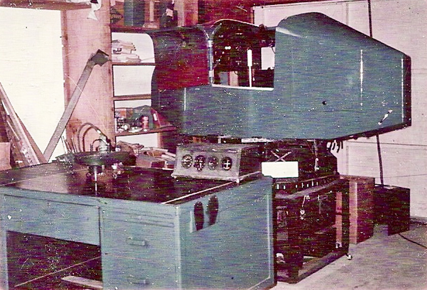
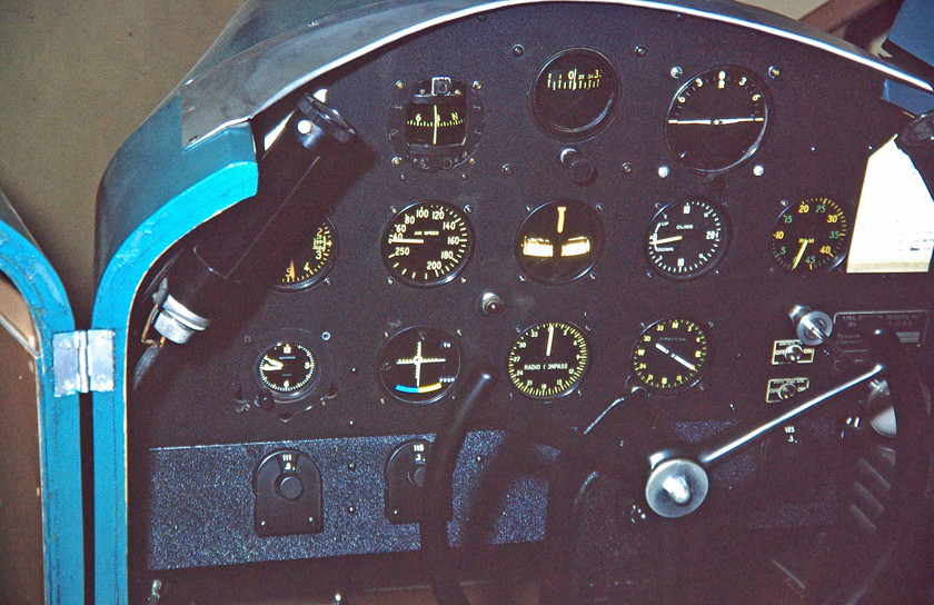
Here is our Link shortly after getting it home. And a view of the instrument panel after some improvements.
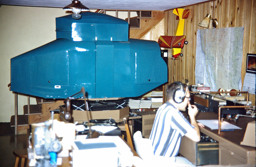
Gene is running a session with a student. The Link just barely fit in his space!
After our days with the Link were over, and home computers arrived, I became interested in computerized flight simulators.
The simulators I used over the next number of years started out very sparse, the first produced just simple line drawings. Over the years frequent new releases kept getting better. I found copies of two of my older simulators and was able to get them running, but not easily! I had an old disk with Microsoft Flight Simulator 5 (MSFS 5) and and the complete factory package of MSFS 2004 (this was in a fancy tin box and was called "A Century of Flight"), and was the last sim I bought until this Covid build. I have found screen shots of all the MSFS sims from 1982 through the present, and show some of them to illustrate the steady improvement in the graphics. The performance and realism also improved. I owned a couple of the other ones, but could find no record of exactly which ones or any trace of the disks they came on. (they were probably on 5 1/4 in diskettes, which I mostly discarded years ago.) I also had (and still have) 2 versions of TRACON, an air traffic controller simulator.
The very first flight simulator for the home computer was written by Bruce Artwick in the late '70s. Interest was high, so he and a partner formed Sub Logic and in 1979 they released the simulator as "FS1 Flight Simulator" for the Apple II computer. As this was an 8 bit computer with only 4k of RAM, the display was only line graphics. Fledgling Microsoft outbid IBM and bought the rights to the simulator, and in 1982 released their first version, Microsoft Flight Simulator (hereafter, MSFS) version 1.0.
The original simulator written by Bruce Artwick was very basic with only 2 instruments and a very simple grid for the landscape, it was the first commercial flight
simulator for home computers. After Microsoft bought the rights, they expanded it and improved the graphics and released it as MSFS 1.0.
Here is the complete list of Microsoft Flight Simulators:
1982 MSFS 1.0 Better detail than Artwick's, more instruments, and optional color
1984 MSFS 2.0 Worked with a joystick and/or a mouse
1986 MSFS for the Macintosh
1988 MSFS 3.0 Better graphics, higher frame rates, and external views of plane.
1989 MSFS 4.0 Included upgraded aircraft, better scenery, random weather.
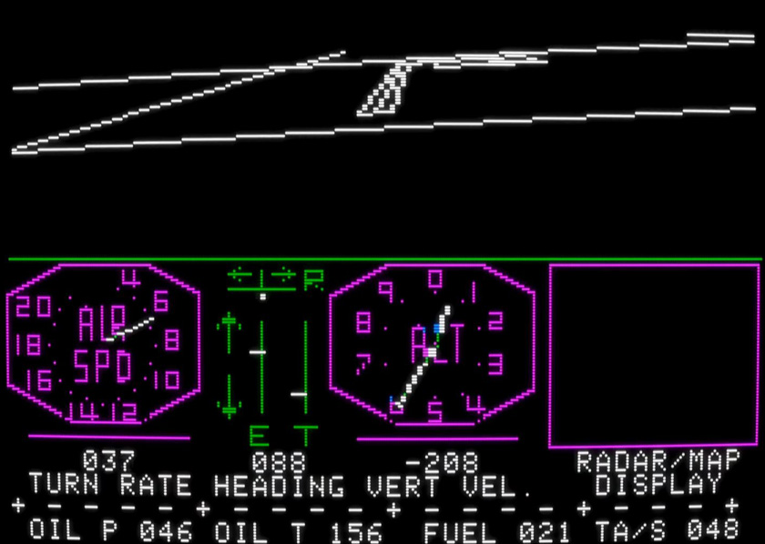
1993 MSFS 5.0 This is the oldest version I found in my files. It introduced textures to the scenery for more realistic views, and had sound effects.
1995 MSFS 5.1 The first revision to come on a CDROM
1996 MSFS for Windows 95 Improved frame rates and added aircraft along with airports outside the US and Europe.
1997 MSFS 98 Sold over 1 million copies, and first to take advantage of 3D graphics using high power graphics cards now available
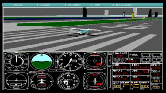
1999 MSFS 2000 Much better graphics, but required high end computer to run smoothly. Added 17,000 airports for a total of 20,000.
2001 MSFS 2002 ATC communications added and AI aided autonomous aircraft flying around.
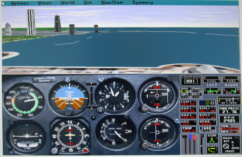
2003 MSFS 2004: A Century of Flight My most recent "archived" version Added historic planes not to be seen again until MSFS 2020 rev. 11
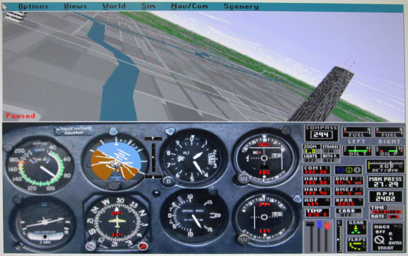
2006 MSFS X Incorporated multi-player flying. It had a huge following and had many 3rd party add-ons
2020 MSFS 2020 14 years after the last release, this is now the version I am using, along with Xplane 11
I have picked a sampling of these releases to show the ever-improving graphics. The performance and capabilities also showed a continuous improvement.
As the versions were released, there was a steady improvement in the graphics, along with features and performance. Here are versions 2.0, 3.0, and 4.0.
In version 3 above (center picture), that is an airplane flying over a river in the very center.
These pictures are of MSFS 5.0, the oldest version I personally still have. I was able to get these pictures by installing a virtual machine on my computer, then loading
Windows 95 into that. I was then able to successfully install the sim.
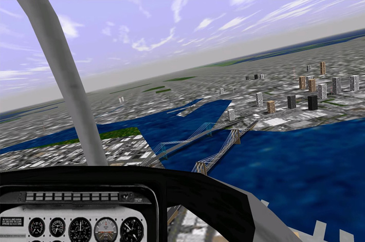
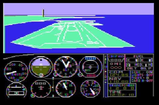
In MSFS2000 the detail was further improved and the scenery looked more realistic, although somewhat "blocky:
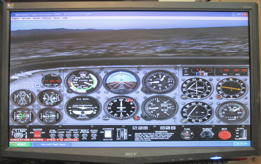
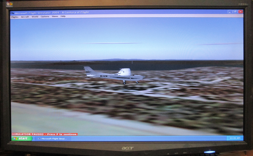
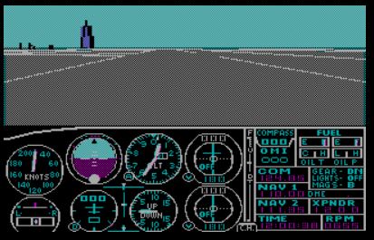
The graphics showed more subtle details in 2004 and became more realistic. The "blockiness" was gone. The instrument panel is also more detailed and realistic.
To install this version, I only had to fire up an old computer still running Windows XP. It then loaded fine.
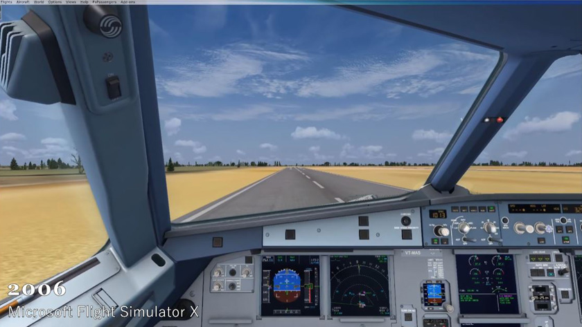
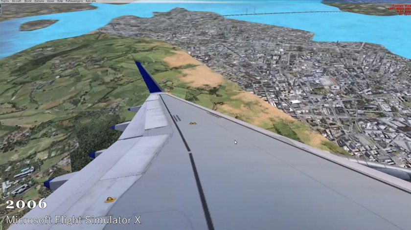
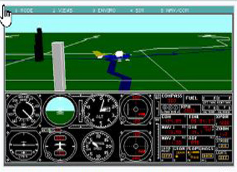
MSFS X had reached a pretty good level of maturity. It had very well modeled aircraft and the landscape was quite detailed (but
not true to life). This version lasted 14 years before the next version and became a fan favorite.
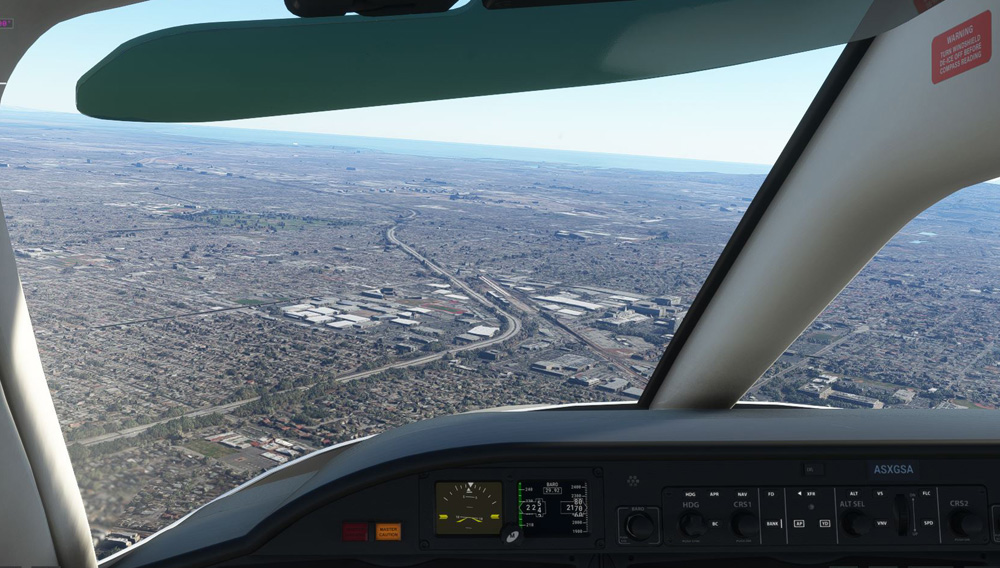
We now have MSFS 2020. Here is a view in the Los Angeles area, near LAX. The detail is unbelievable, both in the aircraft and the
outdoor scenery! Everything on the ground actually exists, each building, road, and tree. I am flying an Icon A5, a
small single engine amphibian.
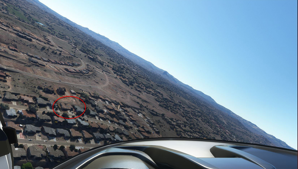
In the same airplane, I flew from the Prescott airport to my neighborhood. I am making a low pass over my house (red circle) and see
the area just as it was several years ago, when the satellite images were actually recorded. Microsoft then took those images, and using
artificial intelligence, created a detailed representation of the entire surface of the Earth, in the format needed for the simulator.
Microsoft's scenery database is about 2 petabytes in size. Only 2, you say? Well 1 petabyte is 1,125,899,906,842,624 bytes! That's over
1000 million million bytes! And twice that is even larger!
We have come a long way in the last 40 years!
This just in! Major MSFS revision 11/13/22
Microsoft just released the 11th revision the MSFS 2020 and it is a biggie! It is their 40th Anniversary edition, released just 40 years after their first flight simulator. In addition to a number of changes which make it run faster and smoother, they added many new bespoke* aircraft and airports. In total they added a very detailed Airbus A310 airliner, 2 helicopters, 2 gliders, and 7 famous historical aircraft along with several historical airports and numerous fields for the gliders and helicopters. This brings the total number of included aircraft to 59. There are many more available from 3rd party companies, but since the prices for these often are about what I paid for the top version of the simulator, and since I am not a that much of a purist, I'm happy with what I have!
*MSFS taught me a new word: Throughout their literature they keep talking about "bespoke airplanes" and "bespoke airports". I finally looked it up. Bespoke is a word found mostly in British English which merely means "custom"! Oh!
The new historical planes include: (Some of these appeared in the 2004 "Century of Flight" release, then disappeared in later versions.)
An additional novelty is an "Easter Egg". If you choose a Diamond DA-62 airplane, then in the cockpit turn on the ELT (Emergency Locator Transmitter). switch, one of the "glass cockpit" screens changes and you can choose to fly any of the first four MSFS versions. A fun touch!
Microsoft just released the 11th revision the MSFS 2020 and it is a biggie! It is their 40th Anniversary edition, released just 40 years after their first flight simulator. In addition to a number of changes which make it run faster and smoother, they added many new bespoke* aircraft and airports. In total they added a very detailed Airbus A310 airliner, 2 helicopters, 2 gliders, and 7 famous historical aircraft along with several historical airports and numerous fields for the gliders and helicopters. This brings the total number of included aircraft to 59. There are many more available from 3rd party companies, but since the prices for these often are about what I paid for the top version of the simulator, and since I am not a that much of a purist, I'm happy with what I have!
*MSFS taught me a new word: Throughout their literature they keep talking about "bespoke airplanes" and "bespoke airports". I finally looked it up. Bespoke is a word found mostly in British English which merely means "custom"! Oh!
The new historical planes include: (Some of these appeared in the 2004 "Century of Flight" release, then disappeared in later versions.)
1903 Wright Flyer
1927 Ryan NYP Spirit of St. Louis
1935 Douglas DC-3
1915 Curtiss JN-4 Jenny
1937 Grumman G-21 Goose
1947 Havilland DHC-2 Beaver
1947 Hughes H-4 Hercules Spruce Goose
1927 Ryan NYP Spirit of St. Louis
1935 Douglas DC-3
1915 Curtiss JN-4 Jenny
1937 Grumman G-21 Goose
1947 Havilland DHC-2 Beaver
1947 Hughes H-4 Hercules Spruce Goose
An additional novelty is an "Easter Egg". If you choose a Diamond DA-62 airplane, then in the cockpit turn on the ELT (Emergency Locator Transmitter). switch, one of the "glass cockpit" screens changes and you can choose to fly any of the first four MSFS versions. A fun touch!
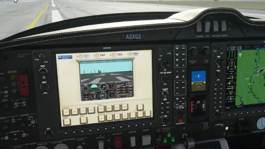
Play with an early version of Flight Simulator while flying in Flight Simulator!
Go back to "3D Print, House, & Misc. Projects"
R. S. Mason November 2022