Tow Car Brakes and Towbar
On a recent trip to an FMCA International Comvention in Albuquerque, I
returned home with a brand new tow car brake system (in the box) from a
convention vendor, and a
near new towbar I spotted on the local Craigslist. This
section discusses the installation of the
braking system, and a modification of the towbar to clear my engine
compartment door.
SMI Air Force One
Braking System
After doing research on the available tow car braking
systems,
I narrowed my search to two units.
The
M&G system is very popular, and does much of what I want in a
system. They have a custom machined cylinder which attaches
between the brake master cylinder and the power brake activator in the
tow car. The cylinder attaches to an air line from the coach
air
brake system and provides sufficient force to actuate the master
cylinder directly. It is totally non-invasive as far as
driving
the car is concerned. The standard system does not include a
breakaway system, but one is available as an option. Two
disadvantages of this system are:
1) The air cylinder is custom
designed for each car, and would require the purchase of a new one when
changing cars. Most, but not all cars can be fitted with the
cylinder.
2) The air system on the coach is not protected
against a failure of the car system, or a broken air line in case of a
car breakaway. If one of these events occur, the coach is
left
with brakes on only 3 wheels.
The SMI Air Force One uses a
clamp-on air cylinder mounted on the brake pedal. The
mounting is
high enough on the pedal that it does not interfere with normal car
driving. Air from the coach creates a vacuum which activates
the
standard car power brake booster. This means the cylinder
does
not need to provide a very high force on the pedal.
The coach is fitted with a small air tank which is
surrounded
with protective
valves such that any break in the car system lines will only empty the
small storage tank, and not interfere in any way with the motorhome
braking. This is the only system on the market which meets
DOT
requirements for this coach system protection. The system
comes
standard with a breakaway system.
This is the system I chose.
|
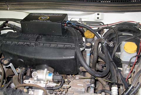
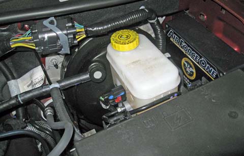
The
control unit of the Air
Force One braking system is mounted
with Velcro on the air cleaner of my Subaru. There really was
no
other practical space that I could find to mount this unit.
There
are lines from the incoming
coach air, and to the brake pedal cylinder and the power brake vacuum.
This
box contains a small air storage tank and the needed valves to
activate the brakes and hold them in case of a car breakaway.
|
I had to mount the air fitting (left) and the
breakaway switch
(center) under the bumper. As the bumper plastic is not too stable, I
mounted them
on reinforcing plates.
The electrical plug is the original one with one added connection.
|
|
|
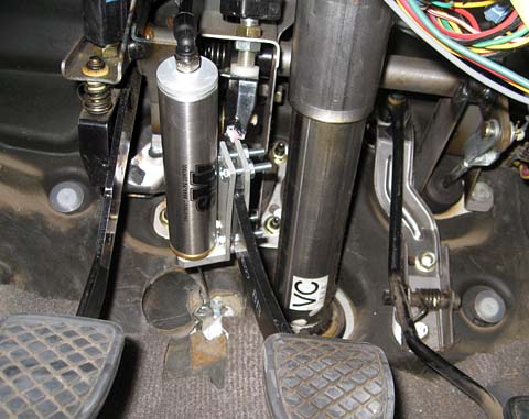
The air cylinder is designed to pull on a small
aircraft cable
when activated. The cylinder mounts on the brake pedal arm
and
the cable is anchored to the floor. When the cylinder
activates,
the cable pulls the pedal down, assisted by the normal power brake
booster. |
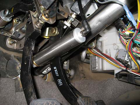
This side view shows the cylinder a little
better.
|
|
|
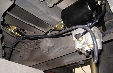
The air brake
isolating
equipment is mounted under the rear of the coach.
The
air tank stores a supply of air from the main supply line. It
is
protected by a special valve. The output goes to a normal air
brake relay valve. The coach pedal air controls the amount of
tank air that is sent to the car.
|
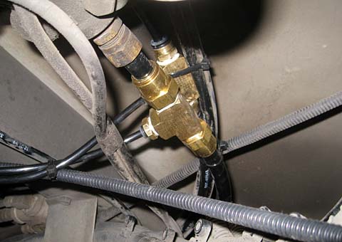
This shows the
fittings that are
used to tap into
the main air supply (bottom fitting) and the modulated air from the
brake pedal (top fitting).
All the fittings are DOT air brake certified fittings.
|
|
The brake
kit came with a small LED assembly which was to be placed on the car or
towbar somewhere where you could see it through the backup camera.
This was
attached to the car brake light circuiit and would illuminate when the
car brakes were applied. As I did not want to mount and
unmount,
and plug and unplug this light each time I used the car, I sent that
signal through a spare pin in the existing electrical connector.
This runs forward to an LED on the dashboard which I had
mounted
long ago when I was having problems with the Air Conditioning.
I
no longer need it for the AC, so am now using it as an annunciator for
the braking system.
|
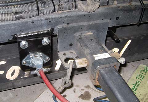
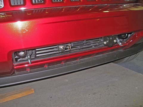
The output from
the air
relay goes to a small fitting to the right of the hitch.
The
power connector on the left had dragged on the ground sometime in the
past, and the bracket was bent outward at about 45 degrees. I
cut
it off, straightened the pieces and overlapped them about an inch.
This makes it an inch less likely to hit bottom again.
I
added a wire from the car brake light switch which runs to an LED on
the dashboard. This indicates when the car brakes are applied.
|
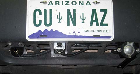
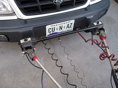
This
is now what the car looks like when it is connected. From
left to
right we have a safety cable, the airline for the brakes, the breakaway
lanyard, the electrical cable, and the other safety cable.
Disconnecting
the air line will not affect the coach braking system, and pulling the
breakaway lanyard will set the car brakes and hold them on. |
 |
I
have tested the braking system and it all works fine. I am
about
to take the rig out on the road, and will verify that it is all doing
what it is supposed to do.
Mods as of 3/9/2011
A
couple of weeks ago I traded in my Subaru Forrester for a new Jeep
Liberty. Of course before turning in the car, I removed the
Air Force
One braking system to transfer over to the Jeep.
I
ordered a
baseplate for the Jeep to connect to my Roadmaster All Terrain tow bar,
and installed it when it arrived. I ran wire in split loom
sleeving and finally managed to feed it all the way back back through
the
frame. I used this to wire the tail and stop lights for
towing.
I originally was going
to mount separate bulbs speciffically for towing, but after looking
carefully at the light assemblies I decided not to, as the new bulbs
would be far from the focal center of the reflectors, and the light
output would be much less. I then opted for the normal diode
isolating method which uses the original bulbs both for normal car
driving, and for towing.
I installed the Air Force
One system in the Jeep. It fit much better than it did in the
Subaru.
There was an open place on the inside of the left front
fender where
the unit fit nicely, in easy reach of the various wires and hoses it
needed to connect to.
The
final step was to mount the air fitting, break-away switch, and the
light connector on the front of the Jeep. The flat horizontal
part of the plastic bumper assembly leading back to the top of the
lower grill was fairly flexible and would be a problem if these items
were simply bolted to it. I decided to back up the mounting
area
with a metal plate. I cut a piece of 3/16 hard aluminum to
about
2 inches by 15 inches. I drilled matching mounting holes in
this
plate and in the bumper, threading the ones in the plate.. I
was
able to fish the plate into the proper area through the lower grill and
maneuver it into place using screw drivers and an ice pick.
Once
aligned, I threaded the mounting bolts through the item to be mounted,
through the bumper, and threaded them into the backing plate.
Loctite on the threads assures continuing tightness.
I was
very pleased with the results. All three items are very
solidly
mounted and show very little flexure as I attach the mating fittings.
 |
The
brake actuating air cylinder mounts on the Jeep brake just like it did
on the Subaru. The main difference is I had no worries about
it
interferring with the clutch pedal, as the Jeep has an automatic
transmission. |
| The Air force One
braking system fit in very nicely on the left front fender.
All the wires and hoses were easy to run. |
 |
 |
This
view shows the tow sockets for the base plate inserts, the safety cable
loops, the air fitting on the left, the break-away switch in the
center, and the light connector on the right. The break-away
switch swings 90 degrees out for towing and stows nicely sideways for
normal driving.
The aluminum plate on the top of the bumper
horizontal section at the top of the lower grill provides a very stable
mounting for the various fittings. |
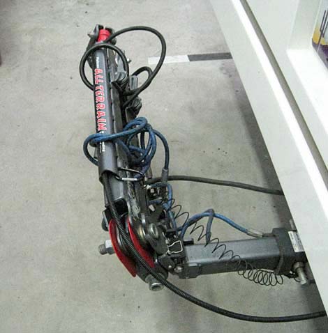
| Here
the Jeep is connected and ready to tow. Shortly after taking
the
towbar picture with the Subaru, I replaced the coil cord
electrical and the coiled air line with straight ones which pass
through the wiring channels of the towbar. This makes the
connection much neater and controls these items better when the towbar
is stowed. |
 |
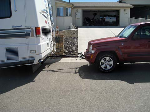 |
A
side view shows the towbar is pretty level without the need for a
dropped or raised receiver on the motor home. By actual
measurement, it is aabout 2.5 inches higher on the car than on the
motorhome. This is within the tolerances called for by
Roadmaster, the maker of my towbar and baseplate. Their specs
are
for the car to be between 3 inches higher and 4 inches lower than the
motor home. Other manufacturers recommend level to 4 inches
lower. I would like to lower the mounting on the car to more
nearly approach level. |
To
accomplish this lowering on the car, I modified how the brackets mount
to the baseplate inserts.
The
bars that insert into the baseplate have flat plates on the front end
with two slotted holes. The piece pictured here bolts to one
of these plates.
The crossbar that the tow bar attaches to slips into this
pair of
plates. The original mounting was by the two slotted holes in
this plate.
To lower the towbar mounting on the car, I drilled
an additional set of holes near the top of this bracket, so that when
bolted to the inserts, the mounting would be lower. |
 |
 |
This shows
the original mounting of the bracket to the insert. Note how
high the bracket extends above the mounting plate. |
| This
is the bracket mounted using the new holes. The net result is
that the mounting for the towbar on the car is about 1 3/4
inches
lower than it was originally, resulting in a towbar that is less than 1
inch higher on the car than it is on the motorhome. |
 |
Addition of 8/30/17
I just sold my Jeep and replaced it with a 1996 Geo
Tracker. Of course this means that I removed the braking system
once again from my present car, this time the Jeep, and installed it in
my "new" car. The details of this change is documented under my
Tracker section and can be seen here:../CarMods/My%201996%20Geo%20Tracker.html
Addition of 3/30/12
Tow Hook
When I first received the Jeep it had a couple of
heavy duty tow
hooks under the front bumper. I guess this is part of the
"Trail
Rated" equipment. I was pleased, as if I am ever in need of
being
pulled out of a ditch, mud, snow, or whatever, this would be a very
convenient place to attach a tow line. I was disappointed
when I
had to remove these hooks to install my towbar baseplate.
I have been thinking of ways I could restore the function of these
hooks if I were to need to. I considered (1) fastening the
hook
to a heavy steel bar machined to duplicate one of the removable towbar
inserts, (2) purchasing a duplicate towbar attachment insert and
attaching the hook directly to it, or (3) making a bracket that would
allow me to attach the hook to the inserts I already have. I
chose the third alternatitive.
I designed a bracket which would drop over the top pin of the existing
inserts with a pin that drops through the bottom hole, just like my
existing towbar crossbar attaches. The folowing photos show
what
I came up with.
|
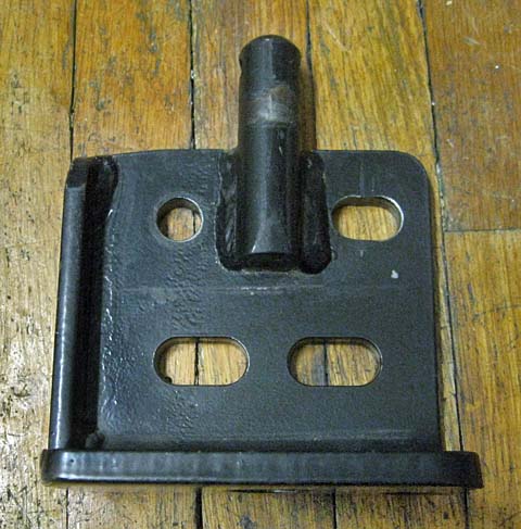
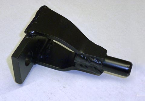
I
machined a 3/8 piece of steel, making a large hole which would drop
over the top pin of the towbar insert, and two smaller holes to mount
the hook. I bent a couple of 1/4 in steel pieces to taper
down
from the 2 inch top plate to the 3/4 inch pin, and welded it all
together.
|
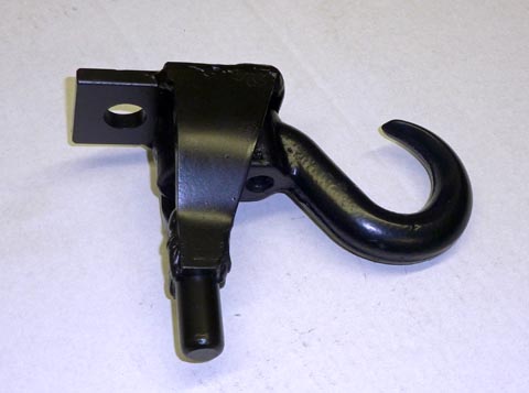
| The
hook bolts to the top plate with its two original bolts. This
shows the assembled bracket and hook, as I will carry it with
me.
|
|

|
Here
I
have inserted one of the towbar inserts into the Jeep baseplate and
dropped the hook assembly over it. It is ready to
use. I
can use the hook on either side insert, and can put a lock through the
hole in the top pin to secure it as I do for my towbar, but for just a
quick pull, even that would not be required.
I thought of mounting the other hook on a 2 inch square hitch bar so I
could put it in my trailer hitch receiver, but decided that the normal
insert with a ball would work just as well If I need to tow someone
else, or if I need a backward tow..
|
Towbar Modification
I
am very well pleased with my new towbar. It is actually two
model
revisions newer than my old one, and certainly in better condition.
The
one problem which I encountered on my old towbar, and then corrected
was that when the towbar is stowed, the engine compartment door hits
the towbar as you open and
close it. On the old design of the towbar, I simply made a
steel
piece with 3 holes, bolted it to the towbar, and pinned to the added
hole when storing it. This allowed the towbar to sit at an
outward angle to the motorhome and provide the needed clearance.
I
want to do the same thing with my new towbar, but the design is totally
different. This bar has a spring loaded latch which engages
the
head of one of the pivot bolts and holds the bar in place. It
is more convenient to use, but is much more difficult to
modify.
I
made a very detailed CAD drawing of that part of the towbar.
I
then rotated the latch mounting assembly 25 degrees around the main
pivot bolt to define what I
needed to end up with. I then designed a welded assembly that
would mount on the old latch holder and provide the rotated latch
holder.
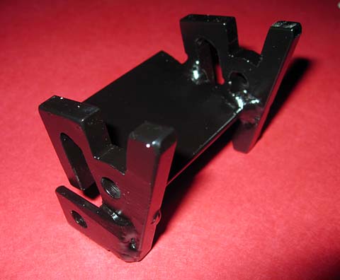
|
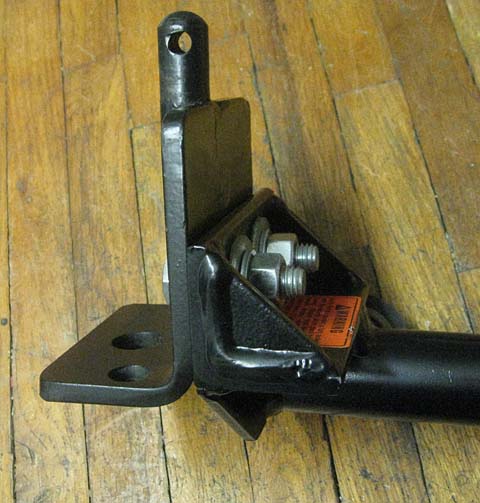
This is the
assembly I made
to re-position the latch to hold the towbar 25 degrees out from the
coach.
It
mounts on the original latch holder, bolts in place, and then provides
a mount for the latch in the new position. It was quite
tricky to
build!
|
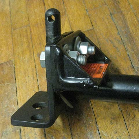
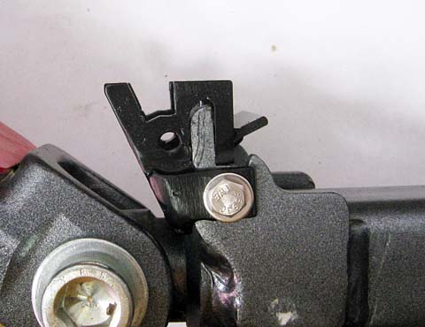
Here
the new latch holder is mounted in place. The latch plate
originally pivoted where the stainless steel bolt is and was spring
loaded against the vertical gray member. You can just see the
right hand stop just above the bolted bracket piece.
The latch
plate now pivots around the empty hole and is spring loaded against the
left member. The spring rests on the 1/8 plate
protruding
at an angle.
The whole latch mounting pattern is duplicated 25 degrees CCW around
the large bolt at the bottom.
As with most of my modifications, the change is totally reversible if I
should decide to sell the towbar or change coaches.
|
|
|
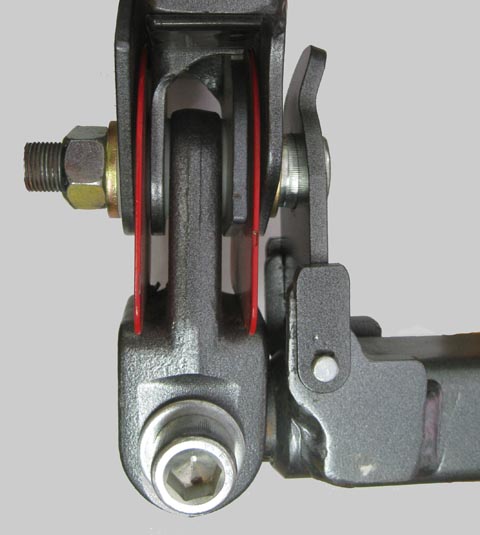
This is
what the folded towbar looked like before any modifications.
|
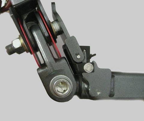
And this
is what it is like now. The 25 degree angle provides enough
clearance that the engine door will now clear it.
|
|
|
Here is the
finished towbar modification. The
bar rests
at a 25 degree angle away from the rear of the motorhome.
This is
just sufficient to clear the large white door on the right as it opens
and closes. |
<BACK>
Dick
Mason, Prescott, AZ
4/16/10