Milling
Machine Motor Replacement, Tach, and VFD
The latest machine to receive a variable speed motor is my
mill. I
started this project by trying to find a good solution for replacing
the motor and by installing a MachTach.
Tachometer
The tachometer posed a problem, as there was no obvious place to locate
reflective strips or magnets for the speed sensor. I thought
about placing reflective strips on the flat areas above one of the step
pulleys, but to avoid interference when changing belt speeds I would
need to place it inside the belt loop between the pulleys.
There
just is no room there. I finally decided to abandon the very
top
step of the spindle pulley and place a ring of magnets there.
I
have not used the top 3 pulleys, and the overdrive capability of the
VFD will allow the next step down to reach a higher speed than the top
step with a normal motor.
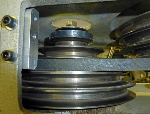
I machined an aluminum ring which is a snug fit around the top pulley,
and epoxied
4 magnets into counterbores around the outside. I then added
a block to mount
a sensor bracket.
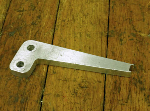
This is the bracket I made to mount the sensor. The slot in
the end is to position the sensor.
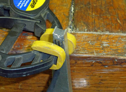
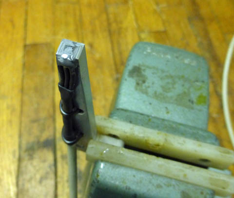
I bent the leads of the sensor a short distance from the body and using
JB Weld, epoxied it into the slot. After the epoxy hardened,
I
carefully dressed
the holder and epoxy to just expose the outline of the sensor.
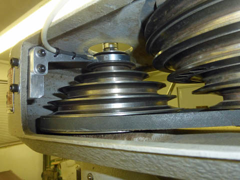
The sensor is mounted in place. There is a slight gap between
the sensor and the ring.
Motor Replacement
There is a problem trying to replace the motor on this machine, as the
original motor has a 4 inch long shaft. It is very hard to
find
"off the shelf" motors with that long a shaft, and I have not been
successful doing so. My alternate options were to buy a
standard
shaft motor and machine a shaft extension, which would then mount the
standard pulley, or to machine a whole new pulley, designed to attach
to a shorter shaft. I delayed doing either, although I did
design two solutions. 1. A custom pulley with 3 of the original 6 pulley steps. I
figured
that with the overdrive capability of the motor, and the fact that I
have never used the top steps of my existing pulley, that that would
suffice. And
2. A shaft extender which would allow me to use the standard pulley on
a standard motor. This is the approach I was favoring.
While I was contemplating these other options, I located a member of
one of the Internet forums who had an original Rockwell 3 phase motor
he was willing to sell, and I bought it. It was in fairly
rough
condition, as it had not been used for some time, and showed some
weathering.
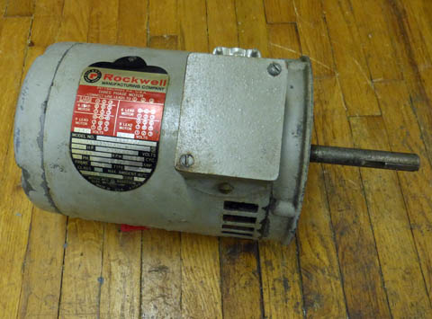
This is the motor as I received it. I connected it to my
lathe
VFD and it ran fine, although there was some bearing noise.
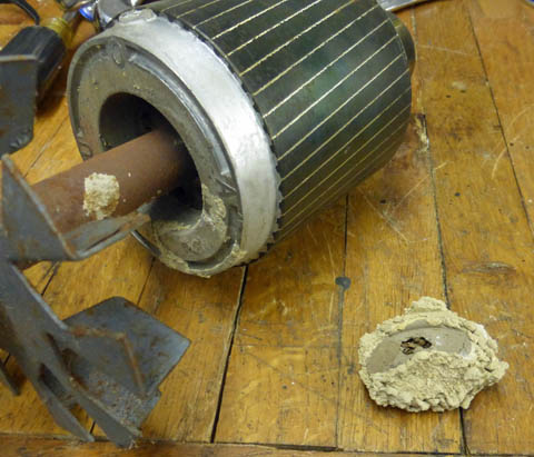
When
I opened it up, I
found
a wasp nest on one end of the armature! It had not dislodged
at
my trial up to 3400 RPM! I guess I should have opened the
motor
first!
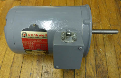
After a thorough cleaning and repainting, and a new set of bearings,
the motor is
looking quite respectable.
VFD and
Control Box
I purchased the same model VFD that I have on my lathe. It is
rated for a 1 HP motor, and this new motor is 3/4 HP, so it is
fine. My original single phase motor was 1/2 HP.
I decided to mount the VFD, the MachTach, and the control switches and
buttons in a single enclosure on the side of the mill. Home
Depot
had a very sturdy 12 x 12 x 6 inch plastic enclosure. I made
an
aluminum panel to hold the various controls and the tachometer, and cut
clearance holes in one end of the enclosure where this
mounted.
All the other components were mounted inside the box.
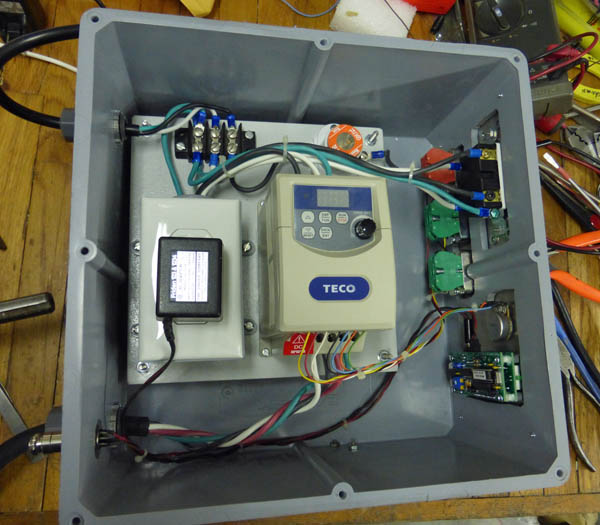
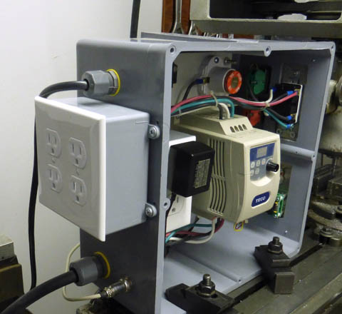
The control box holds pretty much everything. The control
panel is on the right with the power switch and the buttons
on the top, and the MachTach and speed control pot are on the
bottom. The mounting board holds the VFD,
the fuse, a terminal block, and an AC outlet. The tach power
supply plugs in there.
Putting everything in one box really simplified the wiring.
There are only 3 external cables, the AC power cord, the cable
driving the motor, and the tachometer sensor cable, which attaches
using a connector.
I tried to keep the wiring systems separated. The incoming AC
is all at
the top of the case with the control wiring at the bottom center,
going directly to the VFD. The MachTach power and sensor
cables are at the very bottom,
and the motor 3 phase output is also at the
bottom so I kept the power and the tach cables twisted, and
after
installing the box, separated the tach cables as much as possible
from the 3 phase.
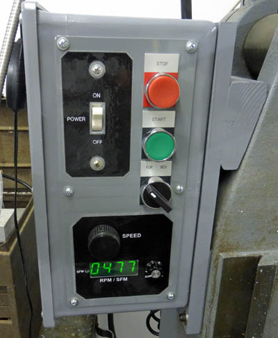
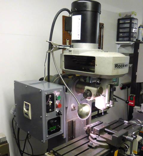
The control panel is mounted to the enclosure, which is mounted to the
mill.
This seems to put all the controls in an easy to reach
location. I kept the STOP
switch at the top, as it would be the last position to be blocked by a
large
fixture or workpiece.
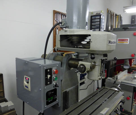
The final installation allows easy access to the VFD for setting
parameters and for viewing
the frequency to the motor. The controls are handy and the
tachometer is easy to see.
Additions
of 6/3/15
The mill has been working great with this motor, however I had
really been planning to modify a new motor with a shaft extender, then
deviated when this motor became available. The new motors
are tailored
to have better performance and efficiency with VFD use. I am
probably being paranoid, since it is running just fine, and there are
many Rockwell mill owners running them on VFD's without any problems.
However, I
decided
to replace the motor with a new "inverter rated" motor, as I was
prepared to do when I saw the offering for the used factory one.
To accomplish this, I
purchased a new 3/4 HP 3 phase motor with the correct mounting on the
face, but with a shorter shaft than needed for this mill. I
had
already designed a shaft adapter to make this type motor work.
I
had also defined several other changes I would like to make to the
control box.
I had originally decided to place the stop button
on the top with the start button below it, figuring if I had a large
workpiece it would be less likely to block the top position.
I
have fought this from day one! The stop button (in my mind,
anyway) belongs BELOW the start button. I made that change
while
I had the box off. I also mounted two duplex outlets on the
rear
of the box, switched by the main power switch to plug in my light,
power feed, and DRO. This way when I turn off the power, I
turn
off ALL the power. I have often left the power feed on and
occasionally the DRO. If I should decide to keep the DRO
powered
on between sessions for a specific project it is easy to replug in into
the wall outlet.
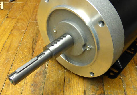
This is the shaft adapter I needed to achieve a 4+ inch long shaft on
my new motor. I
had to cut about 3/8 off the motor shaft for everything to
fit. I used 5 blunt nose
set screws in the shaft keyway instead of trying to machine an internal
keyway. I was
originally going to make the adapter keyway 180 degrees from the set
screws to minimize
runout, but found that between the slight runouts of the adapter and
the pulley, the
present location, coincidentally in line with the set screws, gave me
the least overall runout.
I added 4 outlets on the rear of the box, switched with the main power
switch.
Now, it will be easier to verify that I turn off all the accessories.
I temporarily clamped the box to the mill table for ease of work. Since
it is
wired to the motor, I could not easily take it to my work bench.
Here is the completed modification including the new motor, the revised
control positions,
the outlets on the rear, and a plate for mounting the work light
GO BACK TO "Machine Shop
Projects"
R. S. Mason
12/2013