Home Trips Motor Home
Projects
House Projects  Machine Shop
Projects
Automotive
Projects
Early Computer
Days
About


Adding Power Feed to my Mill


Mill X Axis Power Feed


Another significant project on my mill is the addition of a power feed unit to the X axis.

Power feed allows the machinist to have a very consistent feed rate for the best finish and less fatigue.  It is a standard feature on most lathes, but was only included as an extra price option  on most of the mills when mine was made.  It is still an extra price option for most mills in the lower price ranges.

I have bought a drive which is designed for updating Bridgeport mills or any of the many "look-alike" mills produced by other companies.  Unfortunately, my mill is not a Bridgeport "look-alike".  Although the Rockwell company originally produced a power feed for my unit, they are no longer available and the only units readily and economically available are similar to the one I now have.

There are a couple of approaches to using this drive on my mill.  The most common way is to mount the unit on a custom bracket, machine a shaft extension, and mount a Bridgeport handle and feed dial.  The other approach I have seen is what I am going to do.  A custom housing is made consisting of a rear plate, a U-shaped housing, and a front plate, which supports and surrounds the feed drive.  A custom machined shaft extension mounts the original handle and feed dial.  Modifications are required to a number of the parts, but the original handle and dial are used.

This is the 2nd main project on my mill, the first being the installation of a DRO.  Unfortunately, both these projects have fought for the same real estate in a number of instances.  Since the DRO was done first, it got the prime spots.  The installation of this power feed system had to make several allowances for the items already installed for the DRO.


This is the power feed drive I am installing.


Here is a cross section of what I am making.  Essentially I am moving the handle and graduated dial out and inserting the housing and
the feed mechanism.  Thanks to Jeff K. who designed this mounting system and has installed a similar drive on a mill like mine.  This
cross section was originally drawn by him.  I have since modified it for my use.  Thanks Jeff!

The parts in white are original parts of my mill, with the bearing housing being modified for this application.
In light cyan are the housing parts, the back plate, the housing, and the front plate.  A function of the front plate, in addition
to chip protection, is to hold the index mark to be able to read the graduated feed dial.
The dark blue parts are the power feed unit I bought.  The magenta bearing race and the green gear (shown modified) came with it.
The red part is a custom shaft extension I will need to make.  It is locked securely by the cyan screw.
The yellow parts are the original feed dial and handle with part of the through hole bored out to fit the larger shaft.

Progress:

   
The left hand handle shows the original configuration with the bearing housing containing an index mark so the feed dial can be read.

I have already machined down the right bearing housing to fit within the back housing plate.  I could have made the bearing holder and the back
plate of one piece, but since I am using aluminum I decided to keep the original steel bearing housing.


I started by cutting blanks for the two plates (one shown) and the housing body
from a 4 1/8 inch diameter bar of hard aluminum.


I knew I was in trouble when I used my band saw to rough cut the center housing.
As soon as the blade cut through the first cut, the housing clamped down on the
blade and stopped it short.  After finally extracting the tightly clamped blade and
making the second cut, I discovered that the trapped stresses in the piece had reduced
the diameter by about 0.035 inches.  It was now a tight fit over the feed unit, and
of course it didn't match the front and rear plates..

My solution was to use a spreader unit I made with a bolt, 2 nuts, and 2 oak blocks.
After many tries increasing the spread each time, I finally reached the yield point
at a spread of about 4/10 of an inch.  The end result was that I stretched the housing
back to almost exactly its original dimension, and it fits fine now.


The machining has been completed on the back plate and it has been assembled to the housing.

The left picture shows the rear side.  The bored recess fits around the bearing holder which will be clamped tight to the mill when
this plate is bolted in place

The right picture shows it from the front side.  The feed unit will fill most of the space here.  The 3 countersunk holes mount
the back plate and the bearing holder to the mill.  The four tapped holes are for mounting the power feed unit.


This is the cover.  The back side is shown on the left and the front side on the right.  Note the index mark for
reading the feed dial.


The housing and back plate are mounted to the mill for a test fitting.


And now I have added the power feed drive unit.


Problems

Now that I have actually mounted the drive unit, I can see I have a couple of interferences!  I had not examined the case of the table all the way to the left end and all the way back toward the column.  As it stands now, the back plate of the housing hits one of the Y axis DRO bracket bolt heads at about 7/8 inch before reaching the end of the X travel.  I can reduce the thickness of the DRO bracket and use different screws.  This will reduce the travel reduction, but not eliminate it.

The other problem is that when near the left end of the X travel and moving the Y axis back, the feed motor hits the Z DRO bracket about 1/2 inch before the rear Y limit.  It will hit even earlier if I allow full X travel as above.  This is a much more serious interference, as it can cause a crash with certain combinations of X and Y travel.

I tried a quick fix by adding a new set of mounting holes to the rear plate rotating the entire assembly 25 degrees clockwise.  This swung the bottom of the motor towards the front and helped the interferences significantly, but did not eliminate them.

I decided that the correct way to solve the problem would be to remake the back plate much thicker than the original and remake the shaft extension.  This would move the feed drive farther out from the mill providing more clearance.  The remaining interferences could then be eliminated by reworking the Y and the Z DRO brackets.

In the meantime, I completed the modification of the gear by shortening the gear hub and boring the 5/8 center hole out to 3/4 inch diameter.  This then required cutting a new keyway.  After completing these items, I had a working power feed, even if it was in a very temporary state.


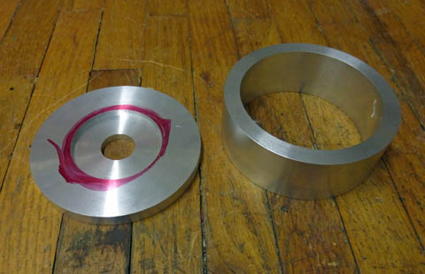
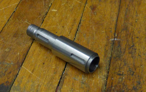
The finished shaft extension is shown on the left.  The reduced diameter on the right end of it is to allow me to use the 5/8 inside diameter gear mesh
adjusting shims that were supplied with the drive.  Making new shims to go over the 3/4 inch shaft would have been a major pain.

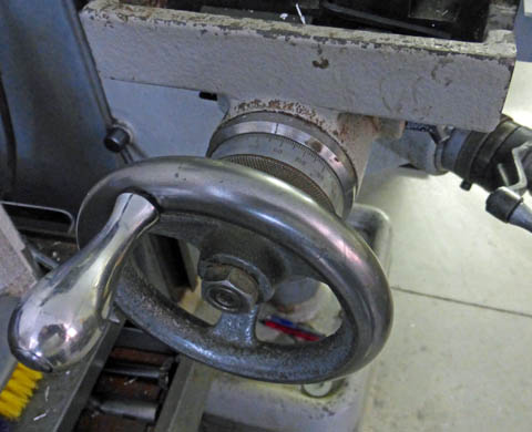
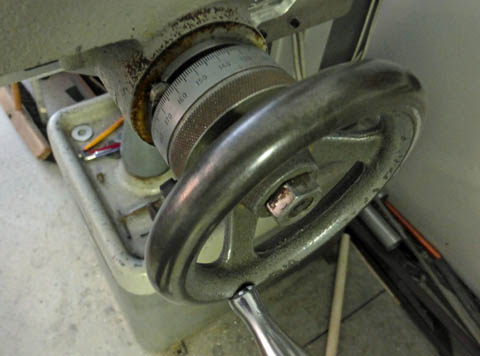
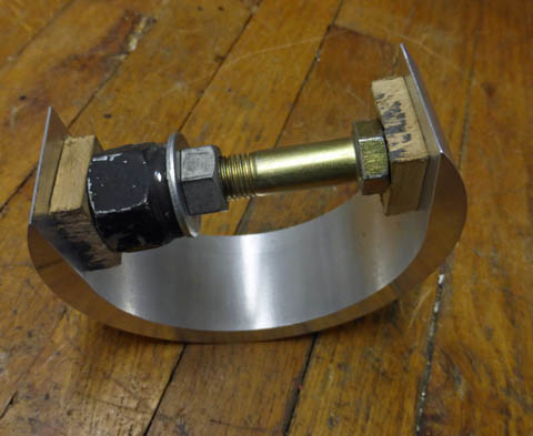
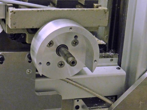
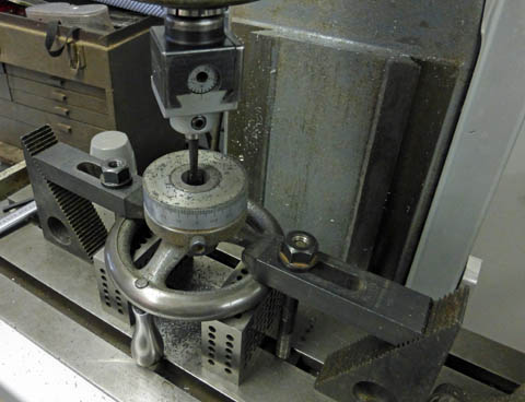
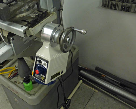
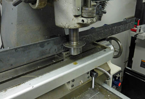
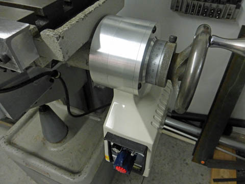
The right picture shows my setup of the crank handle and feed dial for boring a 3/4 inch diameter for the first 7/8 inch of bore length to allow the
handle to fit the larger shaft diameter.  The 2 inch support blocks were high enough only because I was able to drop the crank handle slightly into
the adjacent T slot.


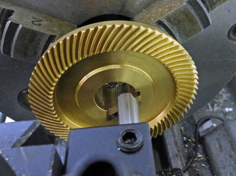
After cutting the gear down in length and boring it out to 3/4 inch, I had to put
in a new keyway.  Not having any broaches (which are very expensive), I
used the "poor man's broach".  Using a 1/8 inch cutter in a boring bar, I cut the
keyway by moving the carriage back and forth.  I advanced the depth by about
.001  per stroke, while the bit slowly cut the keyway.    It worked great!
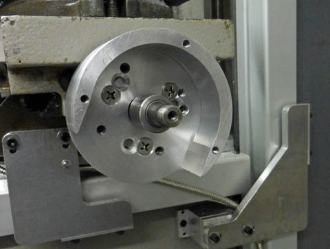
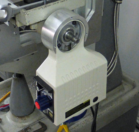


I added a new set of mounting holes to the back plate which rotated the 
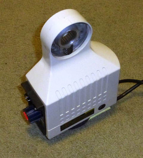
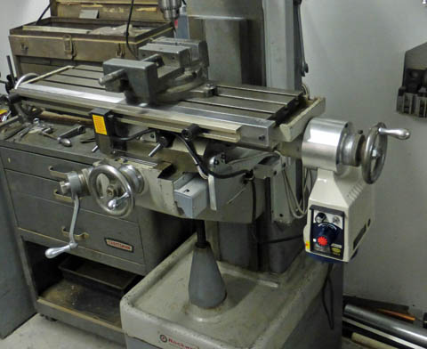
assembly 25 degrees.  And here is the drive fully installed temporarily
at an angle - and it works!  The drive is installed, but there is still a lot of work to do.  I need to make a new thick rear plate and a new shaft
extension.  I also need to modify the Y and Z DRO brackets and provide a means of mounting the limit switches.


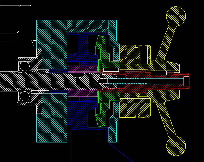
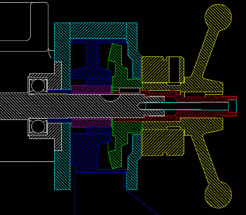
Here is the cross section showing the latest changes.  The back plate is now a full inch thick, moving everything out a little more than
5/8 inch.  I needed a new shaft spacer (dark blue) between the stock bearing spacer and the magenta needle bearing race, and I needed
a totally new shaft extension.  The new shaft extension is exactly the same length as the old one, but overlaps the original shaft less.


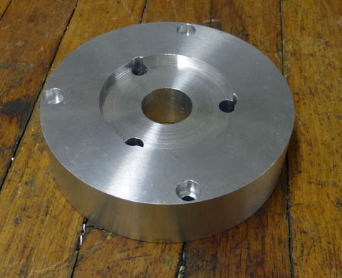
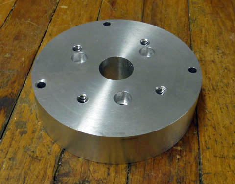
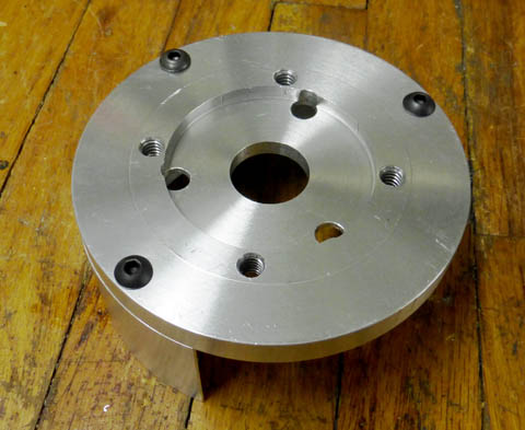
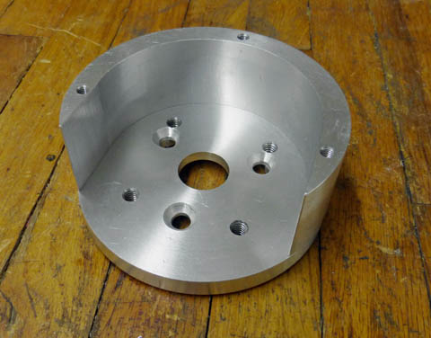
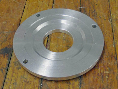
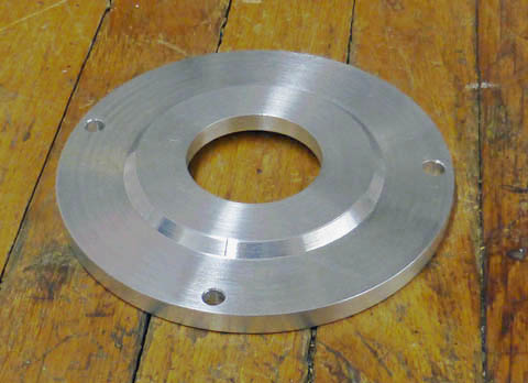
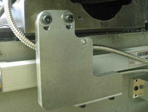
This shows the back and front sides of the new back plate.  The original plate was a little under 3/8 inch thick, this one is 1.00 inch thick,
thus moving the drive about 5/8 of an inch farther out from the machine.


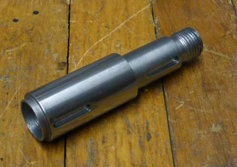
This is the completed new shaft extension.  It is the same length as the original
one, it just overlaps the original shaft about 5/8 of an inch less.
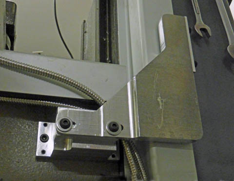


I reworked the Y axis DRO bracket (left) by cutting out the upper right corner and providing a new hole and slot.  This eliminated
an interference with the back plate.

On the right you can see where I removed the bottom edge of the Z DRO bracket, thinned the forward end of it and used low profile
button head screws.  I also removed some of the mounting block corner.  These changes, along with the thicker back plate have eliminated
all interference problems.


The only thing yet to complete on the motor mounting is to replace some temporary screws with the correct ones when they arrive.  I am very disappointed with the big-box stores.  Earlier I tried to buy some socket head cap screws at Home Depot.  They had a couple of pull out drawers with metric SHCS, but no SAE!  I then went to Lowes and found a fairly decent selection and bought what I needed then.  I just went back to pick up a few 10-32 SHCS at Lowes.  The only socket head screws in 10-32 they had was 1 length of a stainless button head screw!  I came home and ordered several sizes from Ebay and am now waiting for them to come.

The rest of the project is to mount the limit switches (one unit - two switches) and the movable lugs that trip them.  I plan to replace the X axis DRO protective cover, which is now light weight aluminum with a 1/8 inch steel angle.  This will attach to the two coolant trays at the end of the table, not in contact with the DRO scale, and mount an aluminum T-slot extrusion which came with my drive kit.  The stock X axis feed kit relies on using the T-slots on the front of the table to mount these lugs, with the switch being mounted on the front of the saddle.  My DRO installation has the X axis scale covering part of the T-slot, making it unusable.  When I ordered my drive kit, I ordered the one for the Y axis.  The drive motors are the same, but this kit came with accessories I thought I could use, including the T-slot extrusions.  I am not very pleased with them, as they are very light weight, but they will do the job.


My first use of the power feed was cutting one leg of an angle I had down to the
correct dimension using a slitting saw.  This was a very slow process, taking 15 or
20 minutes, and I was very glad to let the machine feed the table, while I used my
hands to try and damp the high pitch resonance the saw caused.  This angle will
replace the aluminum one in the foreground.


I have now disassembled the feed unit assembly and re-built it using all the correct
screws.  This should be the final assembly.

After cutting the angle down to the correct dimension, I made two aluminum mounting blocks to mount to the cast drip trays, and installed them all to replace the original aluminum cover.  Unlike the original one, this cover does not contact the measuring scale, and is much stronger than the original.  I then mounted the aluminum T-slot extrusions to the front.  After making a new bracket for the limit switch, I mounted it to the saddle.  I placed the switch offset to the left to leave the DRO trolley bracket fully exposed.  This required mounting the T-slot extrusions slightly offset to the left.  The stop blocks as shown in the following picture are positioned at the extremes of table travel.

I have already thoroughly enjoyed using the power feed making several items (mostly to complete this power feed project).  It is really easy to get used to using it!


This shows the completed installation.


GO BACK TO "Machine Shop Projects"

  
R. S. Mason 1/30/2014