Making a Woodworking Shop
For years I have had, in addition to my machine shop and equipment, some basic wordworking equipment.
It has mostly lived in the front of my garage, as my machine shop is
pretty will filled with other equipment, and I have been reluctant to
contaminate it with all the sawdust. I also resisted any
woodworking projects because they always made a mess of my garage and
cars. This also precipitated a very cluttered area in my garage.
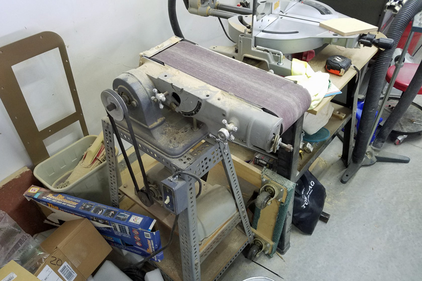
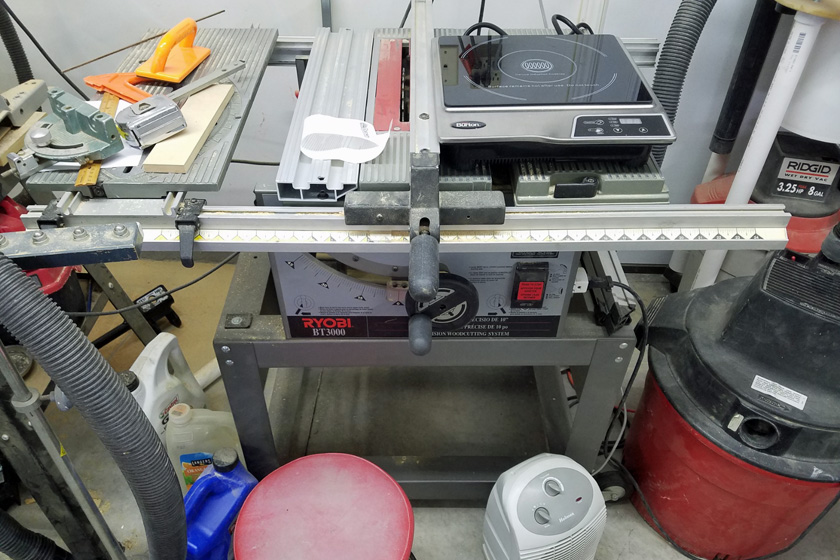
My woodworking machines used to be jammed together at the front of my
garage. This made them almost unusable and the garage a mess!
With the recent sale of my motor home, I suddenly have a huge
(comparatively) area, my motor home garage, now available to me. After cleaning up any
oil spots and removing some duct tape from the floor I had used early on
to guide my parking, I started preparing for converting the area into a
woodworking area. I added lumber racks to the wall and used them to
hold the large pile of jumbled lumber that has been on the floor
against the outer wall for years. I added some electrical outlets
to supplement the original ones. I then moved 2 saws and a sander
from the garage, along with a bandsaw and a hydraulic press from my
machine shop. No, the press is not woodworking related, but is
seldom used and I moved it just to free up space. I also moved items
like a 2 wheel dolly, a furniture dolly and my hydraulic lift cart.
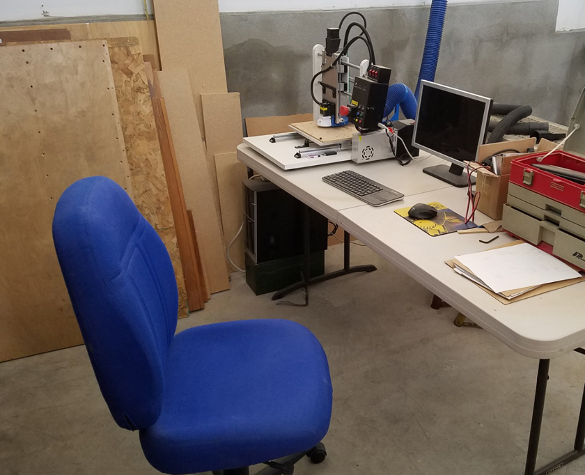
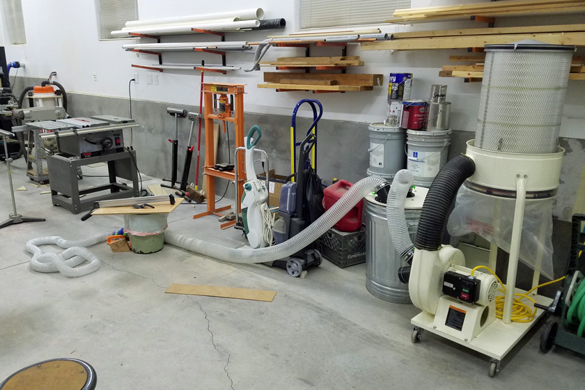
I then set up a table and moved my CNC machine to the back corner of
the room, and made a vent to the outside to exhaust the laser engraving fumes.
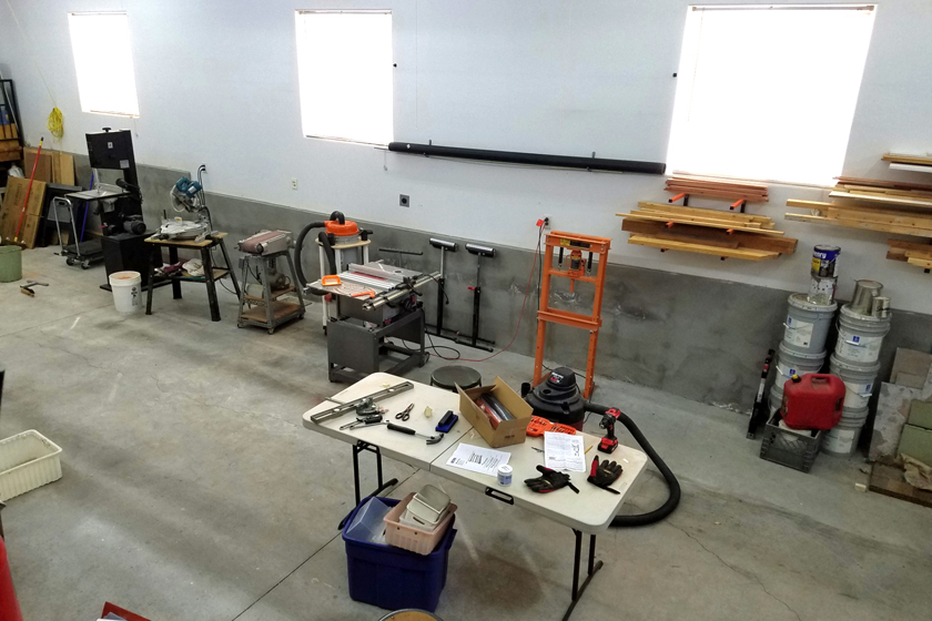
This is a work in progress, but it shows that there is enough space to
actually work with the equipment! I have just set up my CNC
machine, its computer, and a few tools in the rear of the shop.
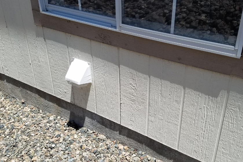
This is the vent to the outside to disperse any fumes and smell when laser engraving or cutting.
Stock rack:
Note: This project took place during the middle of the following
one. For continuity sake, I have separated it out here.
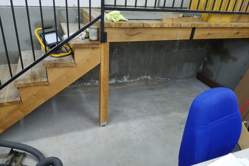
The area where I think the dust collector will best work is filled with
5 gallon paint cans and a pack of roofing, left over from the original
construction, as well as a floor scrubber and a carpet cleaner. As the materials are still in good shape I want to
keep them, but where they are now is no longer suitable. The
process of deciding where I would like to store many items throughout
the area started a chain reaction:
First I pulled the large pile of steel, stainless, aluminum, brass, and
plastic raw material from under the platform at the rear
doors. After sorting this into piles of like materials, I decided
I need another stock rack similar to the one I built in my machine
shop. I used the same technique I described earlier under "Shop
Mods . . . . 2/2018", but I made 8 levels using 8 inch tubes instead of
6 levels with 6 inch tubes. I then mounted it on an open wall
section between two windows.
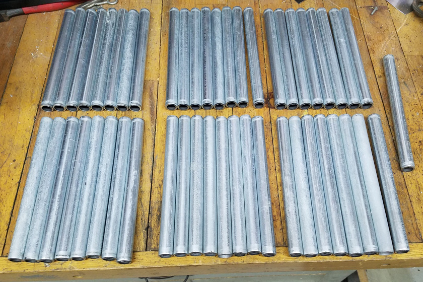
The rack required 48 eight inch lengths of 1/2 inch EMT to be
cut. I pre-marked the cut lines and used the lathe to rotate the tubing while I
cut it with a pipe cutter. Wire brushing the ends eliminated any sharp
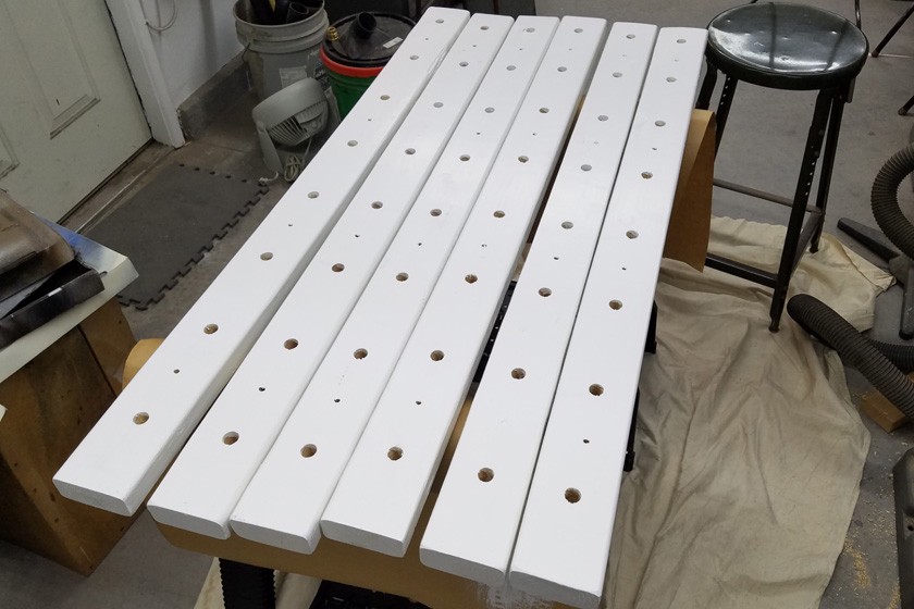
edges. I used a template to position all the holes in the 2x4
mounting strips.
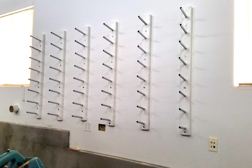
This picture shows the completed rack. To assure proper alignment of the pegs from board to board, I mounted
the two end
pieces, then aligned the others to a taut string between them.
Now to load it! I will use the top couple levels for seldom used
stock, as I will need to use a short ladder or stool to reach them.
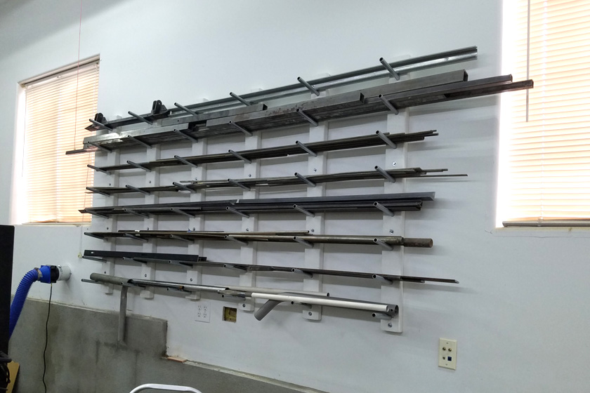
The rack now is holding all the metal from under the platform (except aluminum), and most of the steel from the
machine shop rack. All the aluminum is in the machine shop on that rack.
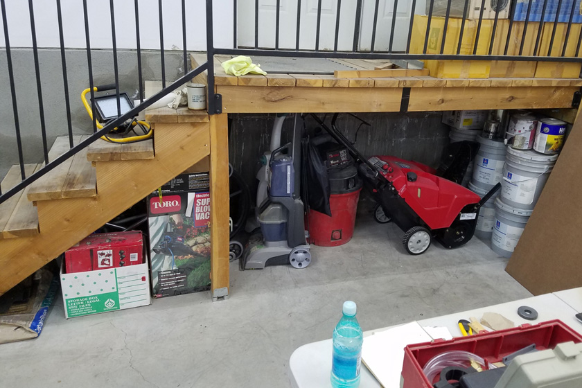
I haven't seen the area under the platform this clean since the
builders left! But that didn't last long! Here I have
loaded it with many items that were just out in
the area. Included are the paint and shingles that started all
this, wheelchair, walkers, snow blower, shop vac, vacuums,
and a couple boxes.
A dust collector:
If I am going to have and use a wood working shop, I need a dust
collector. It is very nice to collect most of the sawdust as you
make it to minimize later cleanup, but that is not the major
reason. The extremely fine dust particles created by many wood working machines are very bad for your
health! They get in the lungs and plug up the small air
receptors, decreasing the lung function. While some of this is
cleared by normal mucus excretions, the extremely fine particles tend to
remain. In general the worst offenders are the particles that are
less than 5 microns in size. Unfortunately this is a very common
limit to the filter bags on affordable dust collectors, which not
only spew the most dangerous particles into the air, but typically at a height where we are more likely to breath it.
I want several things in my dust collector:
- I want a unit capable of filtering down to the sub micron size.
- I want a chip separator which removes the vast majority of
the sawdust (>95%) into a container prior to it even entering the dust
collector proper.
- I want it to be relatively quiet. Yeah, I know, but I can dream!
- I need it to be affordable!
But first, I need to find the dust collector so I can start to modify it.
Harbor Freight sells a very low price unit that thousands have used for
the basis of their systems, often heavily modifying it. At $209,
it sells for less than half of most of its competitors, way less than
some! I tried to buy one and was told (in June) that it would not
be back in stock until October! Thanks again, pandemic!
I then started to look at used ones. After chasing a couple leads
from Craigslist and Facebook Marketplace, I ran into a very good
sounding unit about 100 miles away. His ad asked $250, but when I
contacted him, he said he would take $200. This was for a Jet
brand, which has a very good reputation, and sells new for about
$800! I made a day trip down to look at it, and it looked
great. When we turned it on, the suction seemed weak, and he
admitted that was why he was selling it. He had just purchased it
recently as a used unit, and it would not do his job. I figured
that everything was there, the motor ran well, and that there had to be something simple
reducing the flow, so I offered him $150 and he immediately reached out
and shook my hand. Shortly later while we were eating lunch
before starting back for home, I became convinced that I knew exactly what was wrong. The previous owner had it hard
wired with romex in a conduit exiting the unit. They had just cut
off the conduit and the wire. My seller had connected a regular
line cord to the protruding wires and it had poor performance. I
was sure the previous owner had it connected to run on 240 volts, and
my seller connected it to 120 volts. At half voltage, of course
it had poor performance. Once I got the unit home, I confirmed
that it was truly wired for 240 volts. By moving 2 wires, per the
chart on the inside of the electrical cover, I connected it for 120
volts and it then worked great!
After some cleaning and a little rust removal in the electrical box, I
had a "like-new" dust
collector! And it was a fine brand! The largest problem was
that when new, the standard filter bag was a 30 micron bag, with an
optional 5 micron one. I don't know how to tell which one I
have, but neither of these would be satisfactory. As a solution,
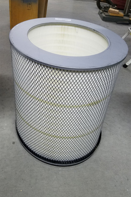
I ordered a MERV 15 filter cartridge (filters very fine particles) to replace the top bag. This
filter removes 99.999% of particles 0.5 micron in size and the vast majority of 0.3 micron ones. In
addition, the pleated construction provides about 250 square feet of
filter area, as opposed to about 16 in a typical bag. This large
area allows a larger volume of air to pass through it. Also,
since the lower bag on the Jet is also fabric, which would allow the smaller
particles to pass, I replaced it with a plastic bag.
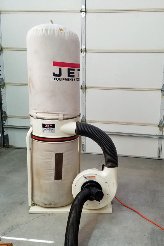
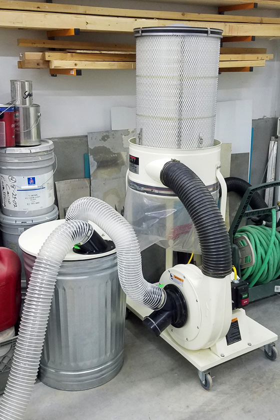
This is my new dust collect in its stock form, after cleaning it up a
bit. On the right is the new filter I purchased to replace the
bags. It filters particles down to 0.3 microns.
Instead of about 15 to 20 square feet of filter area as the original
bag had, the new filter has about 250 square feet of filter in its
pleated design They included a top cover and
mounting hardware for it.
Making a chip separator:
The next step was to make a chip separator. There are several designs in common use:
- A barrel with two elbows in the lid pointing tangentially in
opposite directions. This is a very commonly used design often
using a purchased barrel lid with the elbows built in. It works
quite well when the barrel is not full, but if allowed to fill up, the
turbulence of the air stirs up the pile of sawdust in the barrel,
causing much higher amounts to feed through to the dust collector.
- A cyclone separator. This is a cone shaped tube with the sawdust and air coming
in at the top edge, spinning rapidly around the cone and following the
outer wall down to the bucket. These work very well, but take
quite a lot of space.
- A Thein baffle. Here the sawdust and air circulate
around the outer wall of the barrel (or a special housing) between the
lid and a special baffle plate. This plate has a gap at the outer
edge about 2/3 of the way around. The sawdust traveling around
the outer wall, reaches this gap and falls through to the bottom of the
barrel. The baffle prevents the mixing of the already captured
sawdust, and the unit is effective all the way until the sawdust almost
touches the baffle. The separating efficiency is almost as good
as the venturi, but occupies much less space.
I chose method 3 above.
I bought a 30 gallon steel* garbage can and a 2 x 4 foot piece of 1/2
inch thick MDF. I cut 2 circles from the MDF with the first sized
to be a tight fit inside the top of the can. The second was just
larger than the outside of the can top. These disks were glued
and screwed together for the lid.
*Many Youtubers have built similar separators using plastic barrels,
only to find out that when they restrict the input, the barrel
collapses under the suction.
I designed inlet and outlet pipes to fit the 4 inch vacuum hose and 3D
printed them. That was an adventure in itself! I cut holes
in the lid to fit these pipes, painted the lid, then mounted the
pipes. I then added a length of weather strip around the step at
the lid edge. All joints were sealed with silicone caulk.
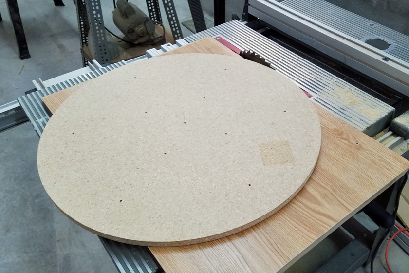
To cut the circles, I made a sled from a board by attaching a cleat on
the bottom which slides in one of the saw table grooves. On this
sled
I put a pin for the MDF to rotate around. This was carefully
positioned on the sled to give the correct diameter. I first used
the sled to slide
the whole assembly to cut pieces off the edge, rotating the disk
slightly between cuts.. When it got down close to the final
diameter I held the
sled fixed and rotated the disk to remove the last very small pieces. The result is a very good circle!
As I was printing the first try of my input pipe, which uses the total
vertical travel of the machine, I noticed that when the Z axis was up
to the maximum of the machine, there were very sharp bends in the
filament. This is because the filament was fed through the top of
the enclosure using a small round bushing. When the extruder was
just a couple inches below the top and way to the side, the bends in
the filament were extreme. My solution was to stop all other
work, design a replacement bushing as a 5 inch long slot, print it and
install it. Further prints then showed only mild bends.
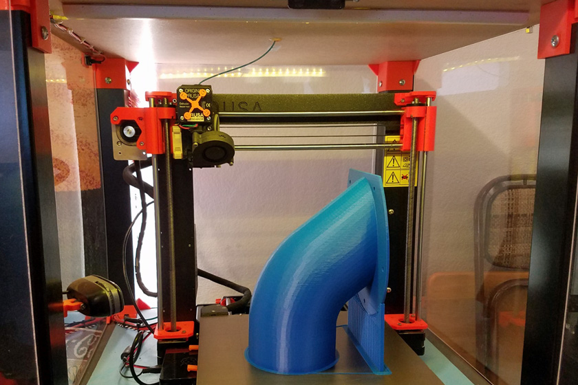
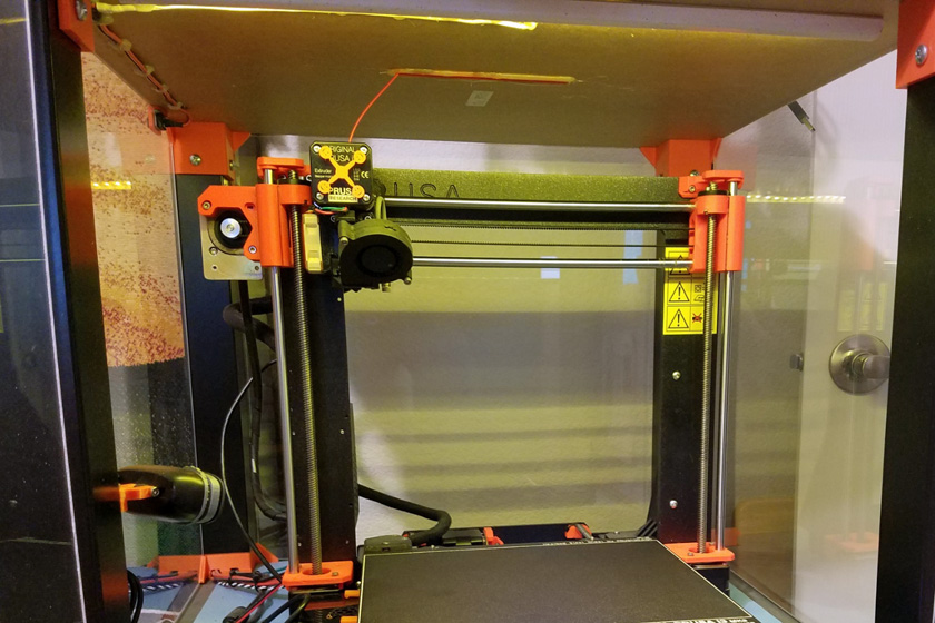
When printing my first trial input pipe, I used the entire rated height
of my printer. At this level I saw a filament path that caused extreme bends in the filament.
The left shows these
very tight bends I then replaced the single hole bushing
through the enclosure top with a slotted one. and the result is much
milder bends as shown on the right.
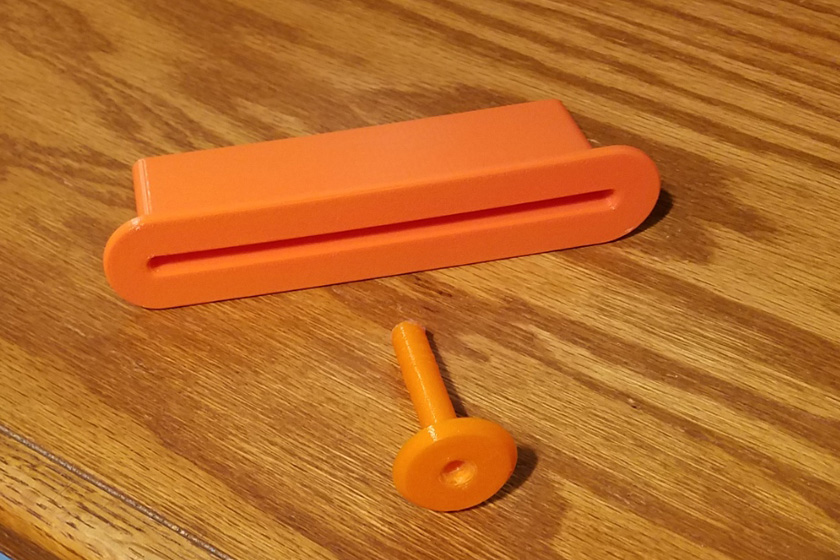
Instead of the filament entering the
enclosure through a single hole in the top, it now enters through a 5 inch long
slot. This allows the filament to run in a much
straighter path, no matter where the printer head is positioned.
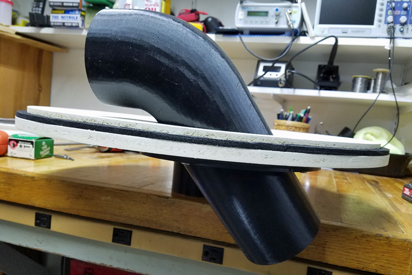
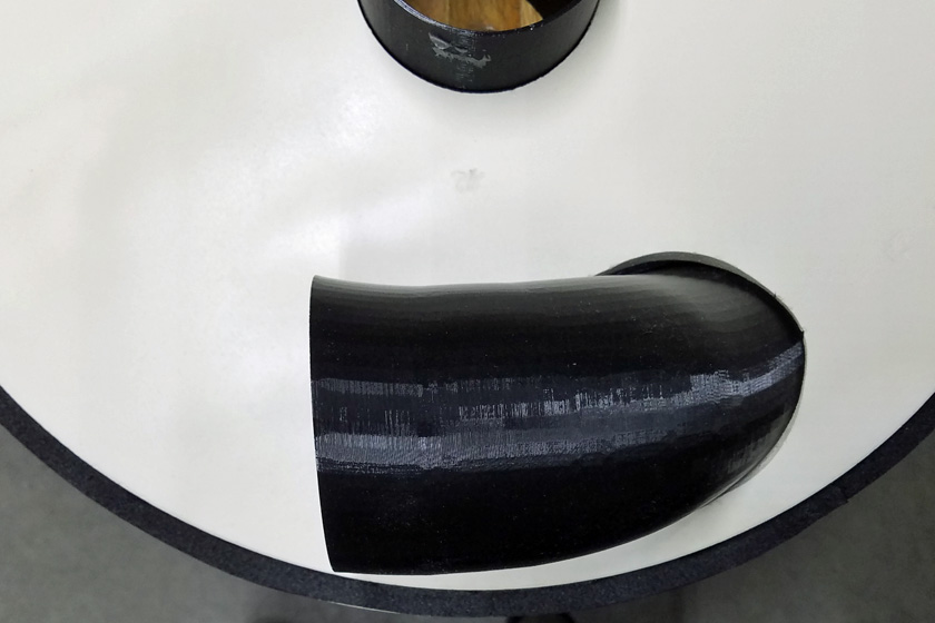
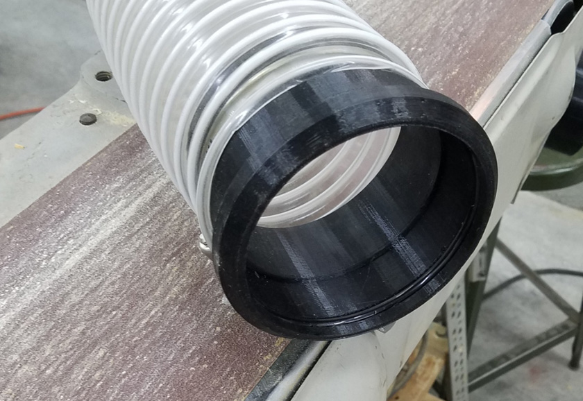
The left picture shows the inlet pipe (upside down) and the edge of the
cover disk. The pipe was printed in two pieces which join at the two
flanges
on the outside of the lid. The right picture shows the curve in the other
axis needed to have the air flow (pretty much) tangential to the
barrel.
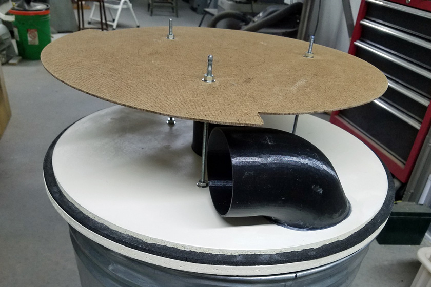
The Thein baffle is mounted to the lid, completing the construction of the separator.
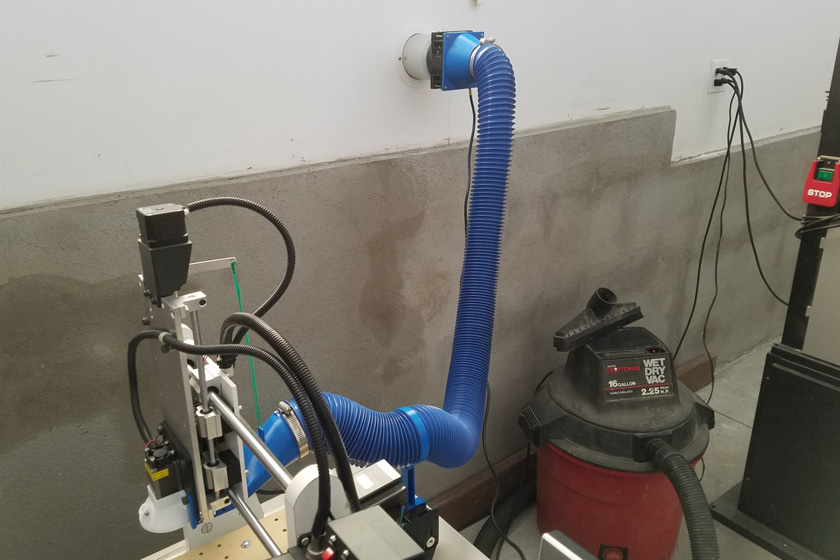
The left shows the completed dust collector system. The barrel
collects about 95 - 98% of the sawdust, and the balance passes through
to the dust
collector and is contained by the cartridge filter that has been fitted
to the top and the bag on the bottom. I cut down the bottom bag
as it
will be filling up very, very slowly.
The right shows about 15 feet of 4 inch hose, connected to 20 feet of 2
1/2 inch hose. I used this to clean up most of the sawdust on the
floor
generated making the parts for the dust collector.
Piping system for dust collector:
I have a very simple shop layout, but I did not want to just run
a flexible hose for each machine, or use a single hose and keep moving
it around. Instead, I ran a single pipe along the wall where the
machines are located. I made two locations for hoses to connect
into this pipe with a blast gate (shop term for a valve) at each.
There is also an extra 4 inch hose port directly on the dust collector
should I want to vacuum that end of the shop, or connect a portable
machine to it in the future.
Dust collectors are different from shop vacs in a couple of ways:
The dust collector has a very high flow rate, but a moderate suction
pressure. A shop vac has a very high suction, but a relatively
low flow rate. According to the experts, my sliding miter saw
will work better with a shop vac, while the remaining ones provide
either better or comparable performance with the dust collector.
Of course the less I can use my shop vac in favor of the dust
collector, the cleaner and healthier my air will be. The shop vac
filter does not remove nearly as much fine material as the dust
collector does.
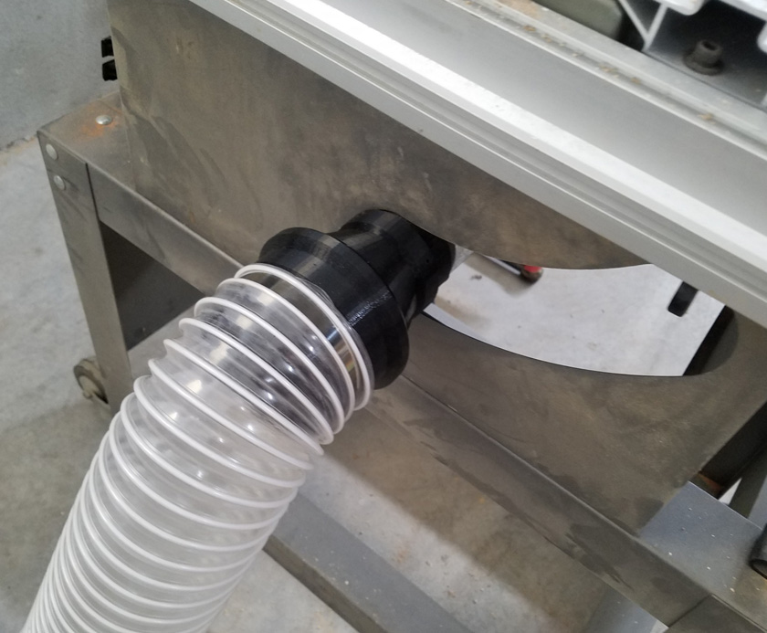
To make connections between the 4 inch (approximate inside diameter) drainage pipe
and the hose, (which fits on a 4 inch outside diameter) I designed and
3D printed a number of custom adapters. I used short lengths of hose
to connect these to the the various other fittings designed for the
hose.
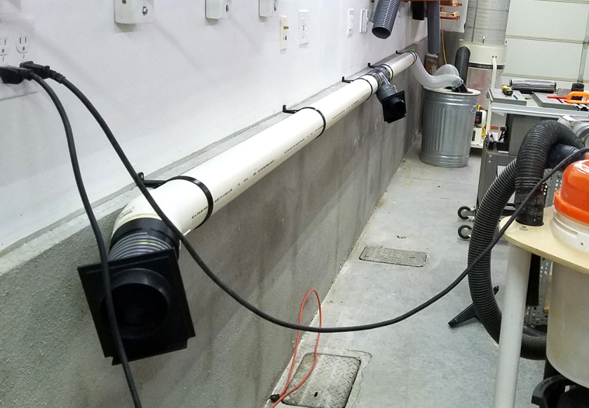
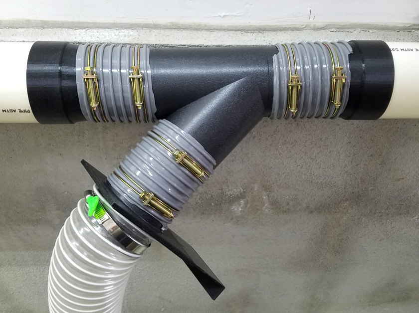
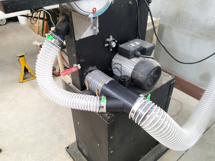
The distribution pipe is run from the dust collector to locations near the tools. I used a number of custom
3D printed parts to put it all together. The two access ports each have a blast gate, which includes a piece of plastic
which can be slid to block the flow, or pulled out until it stops to allow flow. Printed loop straps hold the
pipe in place. The right shows using short lengths of hose to interconnect the factory built wye to the pipe
adapters and to the blast gate.
When it came time to actually connect my machines to the system, I
needed to design and fabricate several other custom adapters.
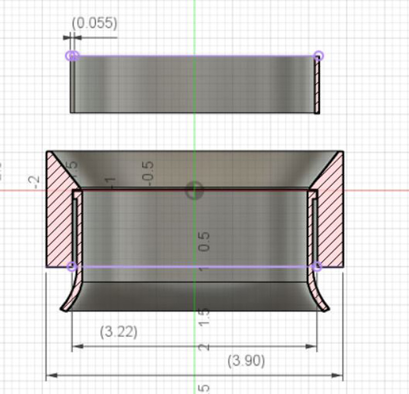
These next few pictures show the cross sections of the parts to better
show the exact shape. A few dimensions were added to these views to help gain perspective.
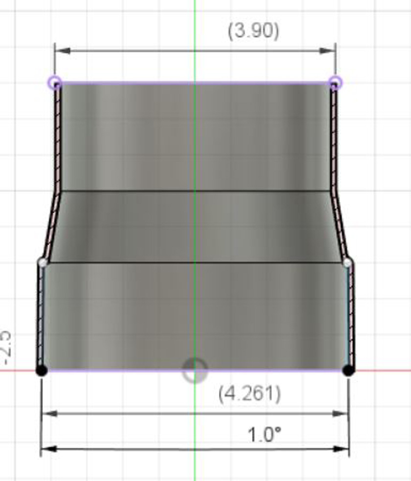
The first one is the irrigation pipe to 4
inch
hose. The pipe end is very slightly tapered so it ends up very tight on the pipe. No cement is used.
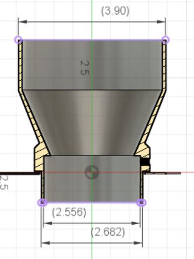
The table saw has a 2 1/2 inch pipe which extends past the sheet metal
by less than 1/2 inch. To give the adapter stability, I extended a very small
diameter well through
the slot in the metal. A pair of set screws attach it through the
thick section. These probably were not needed, as it fit very
tightly over the saw's port.
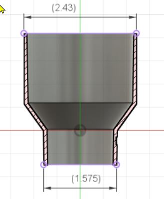
On the right is the sliding miter saw part which adapts the very small
1 1/2 inch port to fit a shop-vac hose. Per multiple articles advising
it, I am keeping
the shop-vac for this saw. If I build a box behind the saw to
capture dust this small port misses, I will connect that to the dust
collector.
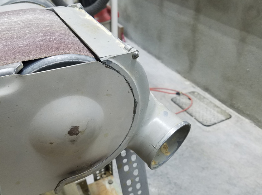
The belt sander was a problem, as the port has a raised ring at the
end, making it hard to attach a part over it and make it stable. To solve this,
I made a
circular split ring which fits over the inner part of the pipe and makes it the same size
as the end ring. The main adapter then fits over this, and is
sealed
with some silicone adhesive.
Since I will be sharing a hose between the belt sander and the table
saw, I need an easy way to move and connect the hose. Originally
I was counting
on hose clamps with a thumb screw to ease this task. I decided to
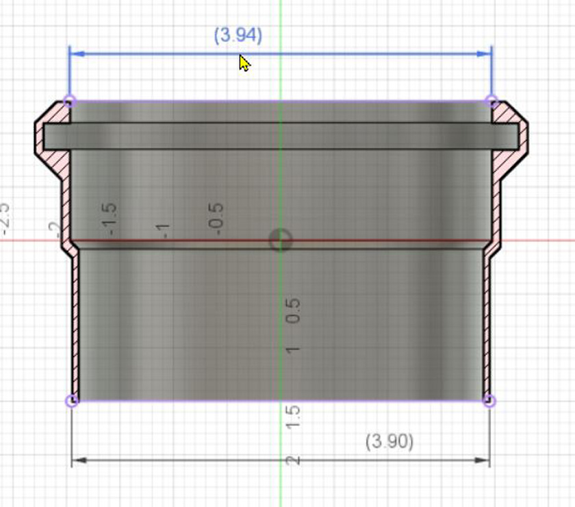
try and make it easier. The right shows a quick connect fitting
which seems to
work quite well. The basic housing is an easy fit over the 4 inch
(actually 3.9 inch) stub. In the end there is a 1/4 inch square
cross section slot. Into
this, I pressed a turn of 1/4 inch nylon air brake hose, cut so there is
no gap where the ends meet. There is just enough give in the
tubing that it is
a firm press over the various adapters, bottoming out when the end of
the adapter hits the diameter reduction. The tubing provides both
the holding
friction and the air seal. I have found that purchased parts
designed to work with 4 inch hose, vary their diameters by about 1/10
of an inch.
The adapter has a very limited range of diameters for it to work, but
as I am building all the parts it will need to work with, I can control that.
The bandsaw with its two ports, did not require any custom adapters. Using a purchased reducing wye, it all connects fine.
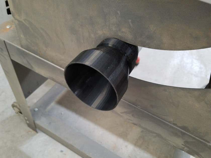
The right shows the adapter fitted to the table saw. Originally,
the 2 1/2 inch pipe only protruded less than 1/2 inch. There
was just enough clearance
in the sheet metal for a small diameter extension to extend well inside the panel to provide stability.
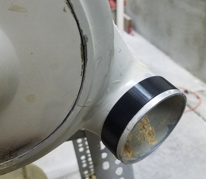
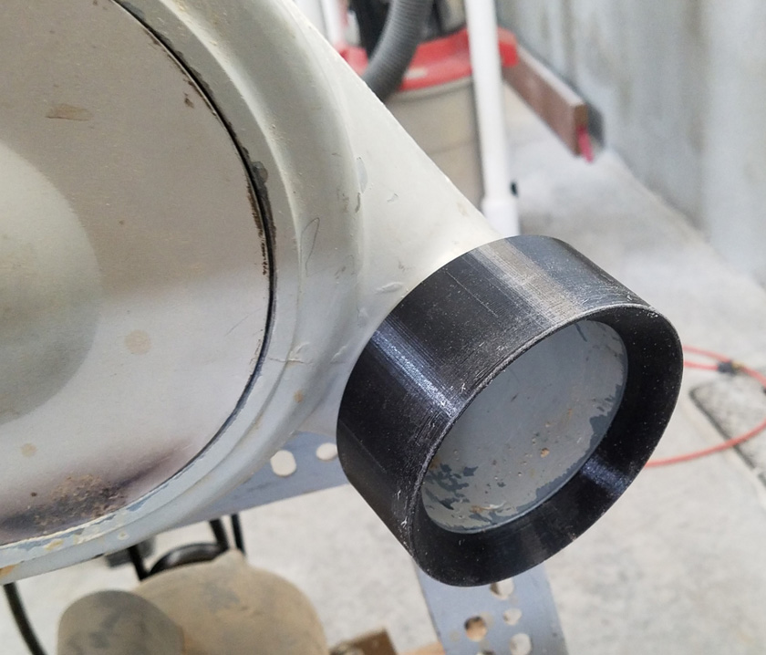
The sander was a problem because of the raised ring at the end of the port.
By using a thin band of plastic around the inner part, a simple adapter
was
slid on and sealed with some silicone adhesive.
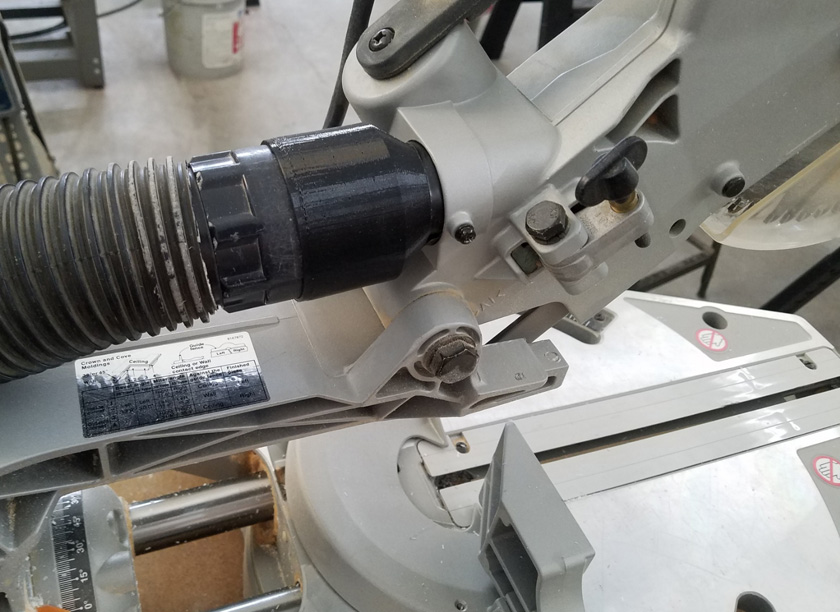
The tiny 1 1/2 inch port on the sliding miter saw dictated using a shop
vac instead of the dust collector. The printed adapter fits the
saw
on one end and a shop vac hose on the other.
The left shows my quick connection adapter. The nylon tubing in the groove near the end grips and seals the connection.
The right shows the quick connect pressed onto the saw adapter.
Remote switches:
Now that I have the dust collector working with all my machines, I need
a way to turn it on and off without having to walk to the end of the
shop where it resides each time. Some new units come with a
wireless remote control (think automobile keyless fob), but I will
settle for a wired solution. I initially thought of using a solid
state relay to control the power going into the dust collector, with a
low voltage, low current circuit with a couple of switches located near
the machines. But I also want to convert it to 240 volt operation
which would require two solid state relays. Then I got back to
common sense design and decided to use a mechanical contactor, a heavy
duty magnetic relay designed for controlling heavy motor loads, and
which switches both sides of the line. There are many available at
reasonable costs as they are commonly used on home furnaces.
I bought a 40 amp contactor and the smallest 24 volt transformer I
could find which supported both 120 volt and 240 volt input. I
already have small switches and connectors, so my main task was to
figure how to house these. My solution was to design and print a
housing to fasten to the top of the existing control box. Making
it the same width just fit these two main components, but I had to make
the box deeper. It will overhang the existing box about 1/2 inch
in the rear.
I also did some re-arranging of the main control box. I moved the
power cord to the bottom of the box, where it had been
originally. I also decided to replace the large 2 push button
power switch which when I received the unit probably had the most rust of any
component. I cleaned it up pretty well, but am not sure of the
inside. By replacing this switch with a much smaller commercial 2
pole 20 amp toggle switch, I gained considerable space in the box, both
on the rear and on the sides. This also allowed me to add a 3
circuit terminal block to simplify the motor wiring and allow easy
voltage changes.
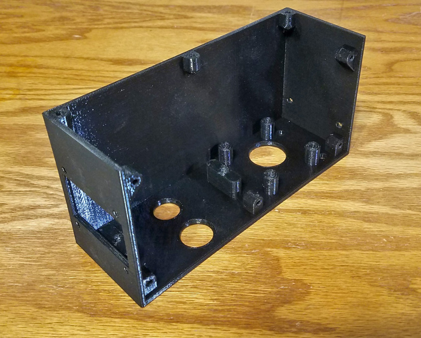
The printed housing for the transformer and contactor has all the mounting pads and threaded holes needed
to mount the parts and the cover. This is the first time I had printed all the threads for this type of an application.
The cover sits flat on the top, but is inset flush on the front.
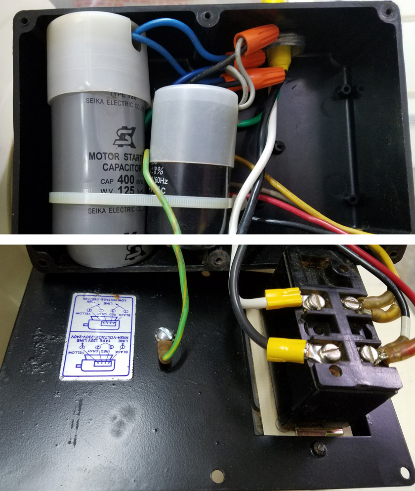
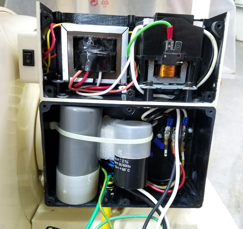
The control box before modifications is shown here in the form of 2 photos which together pretty well show the various fits and
clearances. The massive power switch on the plate at the bottom
took pretty much the entire depth of the box, was quite wide to
begin with, and with the side pointing wires in the only possible position, made it require even more clear width.
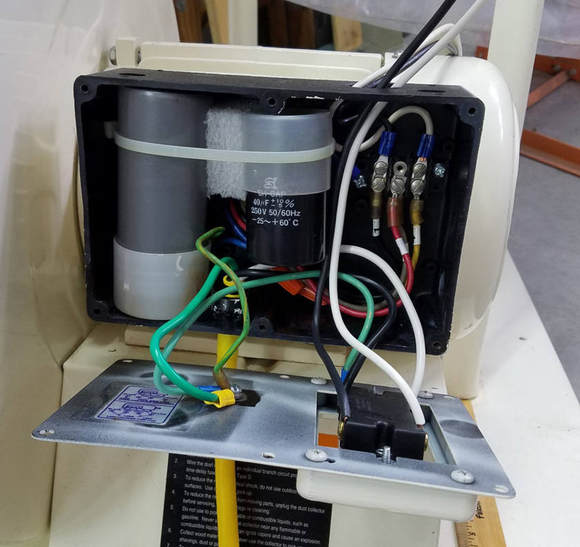
By replacing the switch with a commercial grade 2 pole toggle switch,
mounting it on an extender needed to correct for a different mounting
pattern, and
the wires exiting the back side, there was far more room in the box, both along
side and behind the switch. The small capacitor has been moved to the
right making room for the line cord, now entering from the bottom and the ground wires. There was also
room for a small terminal block simplifying
changing the motor voltage.
The right shows the new box mounted to the top of the old one with
all components in and wired. Since the original control box was
black, I made the new
one black also. I then decided it would look better as a
matching beige, so I painted all the parts. It would have been a
lot easier to get the paint to
cover if I had
printed with a light color. Isn't afterthought
great?
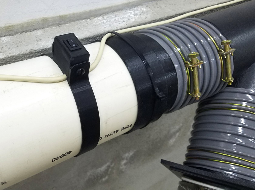
Two remote switches are mounted, one at each blast gate location. Either of these switches, or
the one on the control box can turn the dust collector on or off. They are mounted in a custom
designed and printed box and strap combination.
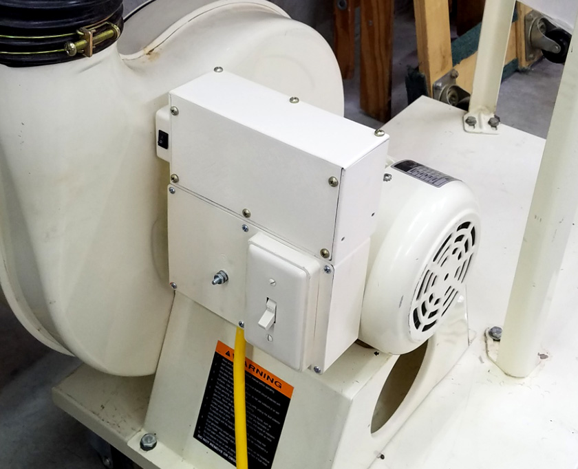
And here is the completed unit fully tested and ready for operation. The small housing on the left side
contains the connector for the external switches on its top, and a switch on the front which simulates
having an external switch on. This allows stand alone operation while still allowing for external switches.
Remote Switch Mods of December 2021
Although the remote switches functioned perfectly, it turned out they
were very inconvenient to use! The two locations I chose, one at each
blast gate, just were never within reach when I needed them. I
always had to snake my way around a machine and over a hose to reach
them. It didn't take long for me to start rethinking the switches
themselves. All the supporting equipment, the contactor, power
supply, and housings, were fine as is.
Several months ago, I was given 3 vertical blind top units to dispose
of. They were far too long to fit in the city trash barrels, and I
volunteered to cut them up to fit. Each of these units had an
aluminum rod which ran the length of the blinds, and had a cross
section like an 8 tooth gear. They were each almost 8 feet
long. Before cutting up the assemblies for disposal, I removed these rods as
something I might be able to use someday. Today is that day!
I decided to run these rods along the wall, over the length of dust
collector pipe, with a number of "toggle switch" type levers spaced
along the length, with the bar operating a switch at one end to turn
the system on and off. Moving any of these toggles through a 90 degree swing will turn the system on or off.
My first problem was to design a 3d printed toothed hole which would
snugly fit my aluminum rods. I carefully measured the rod and
designed a "matching" hole. After several test prints and
adjustments to the design I had a toothed hole which fit quite well
with a light drag as I positioned it on the rod. I now used this
form on all the parts which needed to fit the rod.
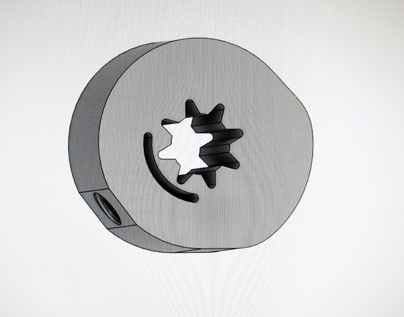
The switch actuating cam, shown here as a photo from my CAD program, shows the star shaped hole. This fits
snugly over the rod and is held in place by a setscrew. I did not want the setscrew to bottom on the rod itself,
as it would distort and burr the rod probably making it impossible to later remove the part. Instead, I formed
a narrow slot so the setscrew would bottom against plastic, pressing it tight against the rod.
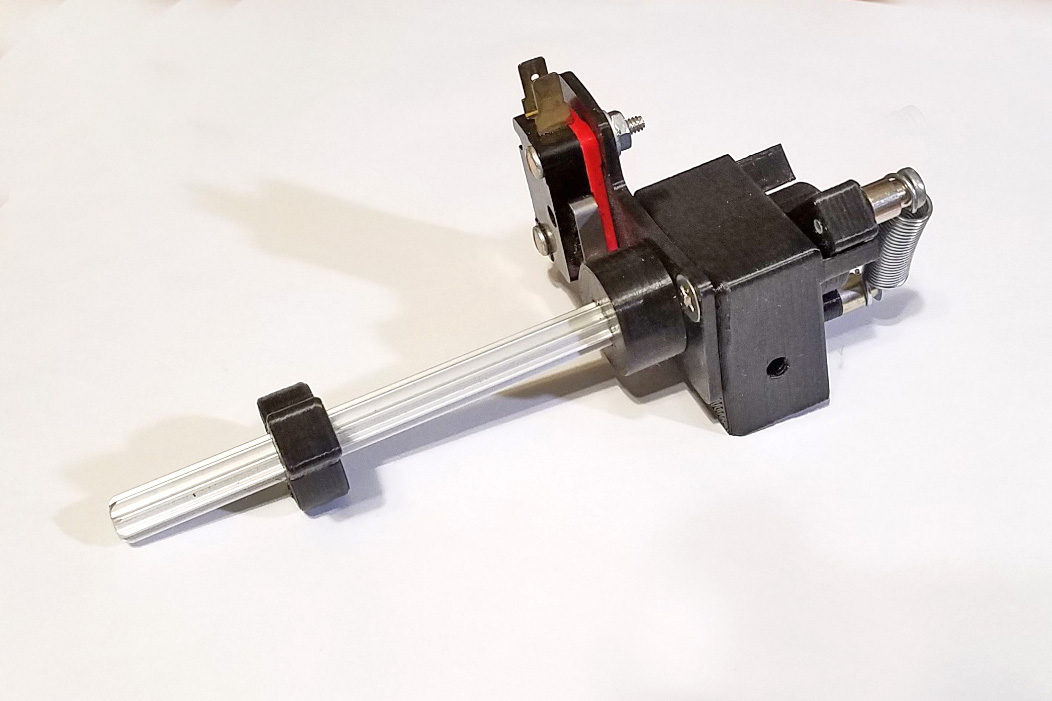
The completed switch assembly consists of a block with an over-center spring on one side and a cam operated micro switch on
the other. Turning the rod 90 degrees from stop to stop turns the
cam which turns the switch on at one position and off at the other.
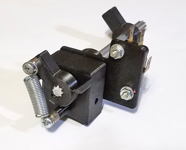
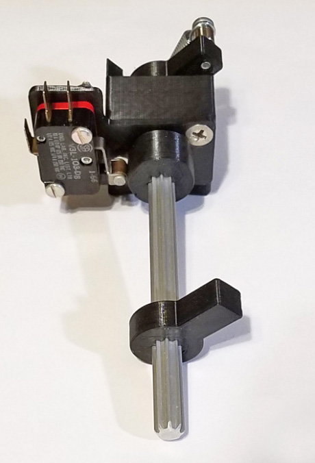
The left shows the spring over-center parts and the stops on the
block. The spring assures that the rod will stay at one stop or
the other.
The right shows the cam and the micro switch it actuates. In the
foreground is one of the many toggles used to turn the system on or off.
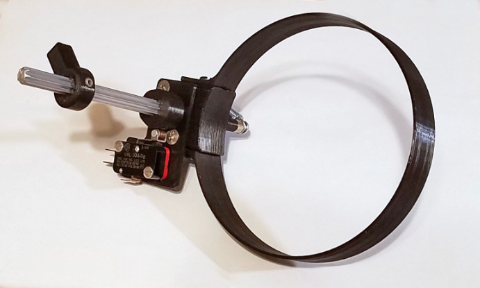
The completed assembly contains a strap to securely hold the unit in position on the collector duct.
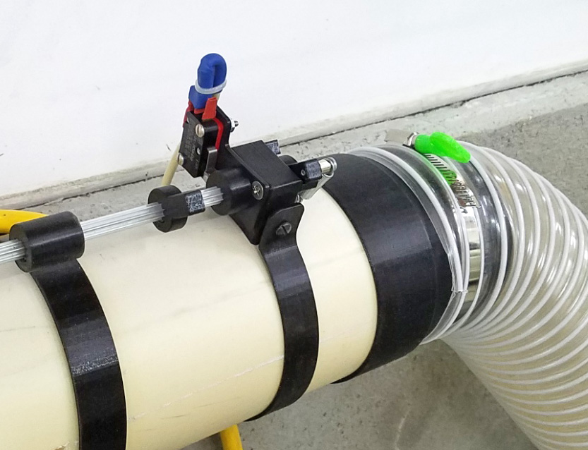
Here it is assembled to the ducting.
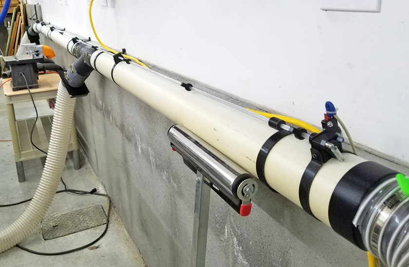
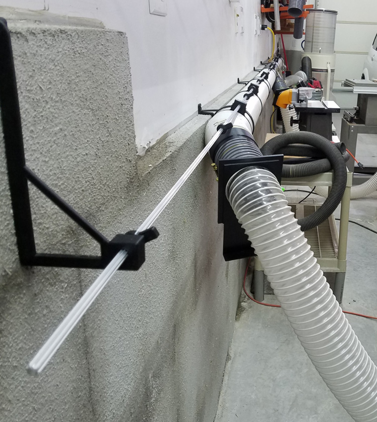
And here is the final system. I extended the rod well beyond the
ducting to allow easy access from my bandsaw. In all, there are
10 toggles along the length of the rod, spaced
between 20 and 23 inches
apart to allow easy access from any point along the rod.
Conclusions:
I had my choice of many ways to accomplish this task. Many
commercial units come with an RF remote control which you can carry
with you to operate the dust collector. A neighbor who operates a
serious wood shop, doing commercial work, has this system. He
states that the remote is always at the other end of the shop when he
needs it, and it may be under or behind something and he has no idea
where it is. I did not want this. I could have just
increased the number of switches along the ducting and included
switches on longer cords to locate directly on the machines. This
probably would have been a better system in the long run, but I decided
I wanted to do something mechanical and when I recalled the vertical
blind rods, it all fell into place. Any other options can
certainly be added to this system with no impact on what I have already
completed, but at this time, I see no reason to. I am happy!