Automating a Dividing Head
The Challenge:
I have a dividing head in my machine shop, which by nature, is tedious to use and is error prone for an operator who seldom uses it (me). A dividing head is a tool containing a spindle and a chuck which you mount on a mill (or occasionally a drill press). The part to be machined is clamped in the chuck which can then be rotated very accurately to a desired angle, usually in the form of dividing a single rotation into a specific number of equal angles. This can be used to make simple parts such as the six sided head of a bolt, or more complicated things such as machining the teeth of a gear, one at a time.
The largest problem I have found using mine is the difficulty of use and the large potential for error. To set it up for a job, you must first look up in a large table for the number of stops you need in 1 rotation of the chuck (there is also a formula you could use). It will tell you to use an index plate with a ring of a certain number of holes. My machine has 3 plates to cover a wide range of values. After you set the crank to line up with the correct ring of holes, you look up how many turns of the crank, which makes 40 turns for one of the chuck, plus how many additional holes you need it to turn. Doing this will make one of the moves. You also should lock the spindle before machining, and unlock it again before making the next move. This process is repeated for each increment needed until complete. To assist in counting the extra holes, there is a V shaped guide against the index plate. This can be set to span the correct number of extra holes to eliminate counting them each move. Of course you have to remember to advance the V before turning the crank again. With my infrequent use of this tool, I have had to re-train my muscle memory to perform every step in this process each time I use it. I have also in the past, failed to pull the pin on the crank back far enough to clear the V guide and it get dragged as I turn. If that happens you have lost your location and need to re-establish it before proceeding. This is often not an easy process!
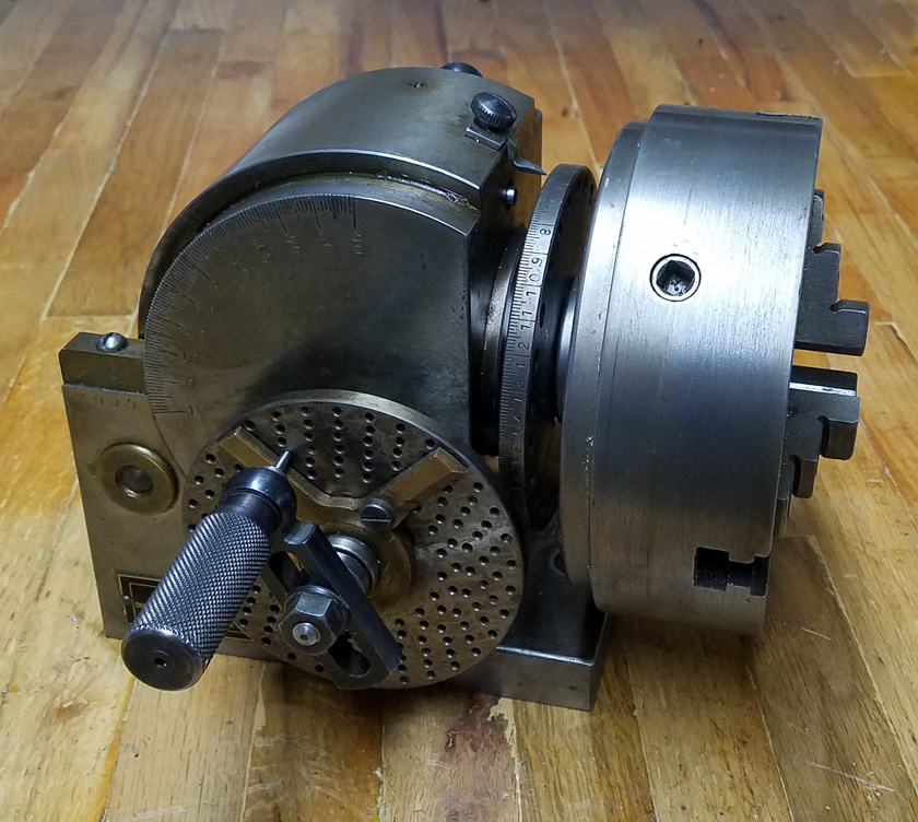
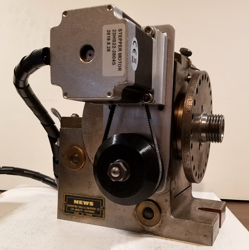
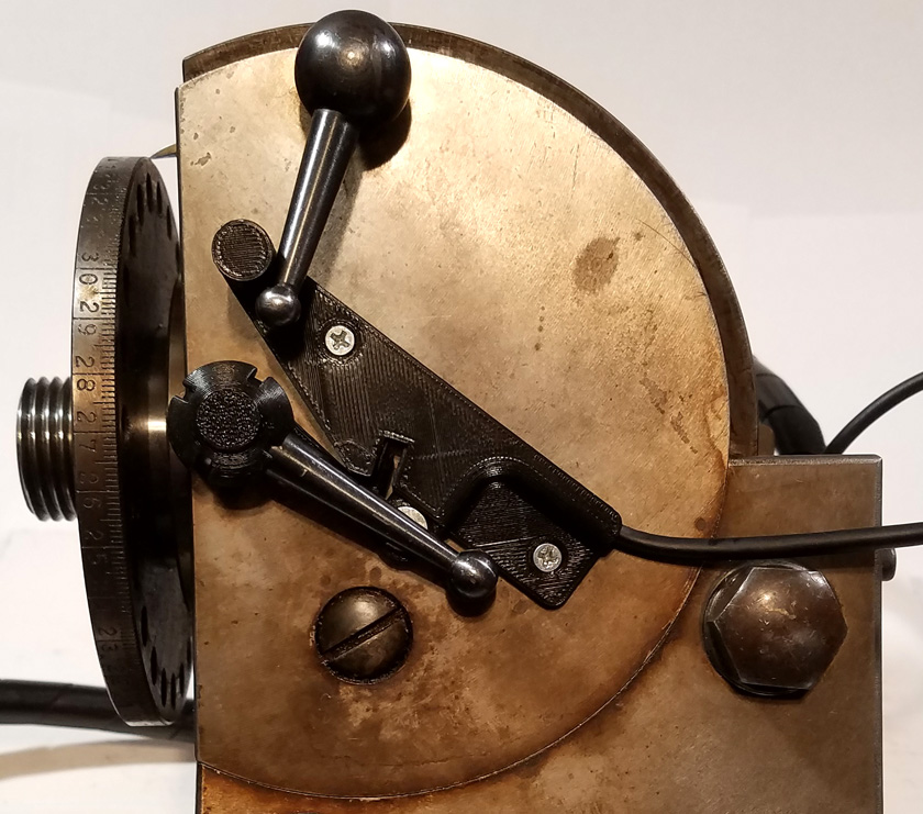
This is the dividing head I am modifying. Note the crank with a pin that can be adjusted to line up with any ring
of differing numbers of holes. It is spring loaded and needs to be pulled out to turn it. The V shaped tool can be
adjusted to keep from having to count the holes each move.
My Plan:
What I want to do is somehow attach a stepper motor to the device and drive it with an Arduino micro-controller. This will not only make the operation very much simpler, but also more versatile. By eliminating the need to look up values in a book or chart, and eliminating the restrictions of only having a finite number of hole rings to chose from, operation will be simple. I plan to design the controller to allow incremental moves of any angle, specified to two decimal places, i.e. 28.45 degrees. It will also allow any number of equal moves to well above what is practical to machine. The basic resolution of the machine will be in the 100s of thousands of steps per revolution of the chuck. I am sure that this resolution well exceeds the basic accuracy of the machine.
I started by measuring the approximate torque required to turn the crank using a rather crude technique. I pressed up on the crank with a small scale, measuring the force required to start turning the crank from one of the tightest locations. I decided that the torque provided by a NEMA 17 stepping motor (typical on 3D printers) would be too marginal so I decided on a NEMA 23 motor. This has many times the torque of the smaller motor. I ordered the motor and a driver module and figured I would be able to design a satisfactory mount and enclosure as required. As it turned out, after cleaning and re-lubricating the gearing, the torque needed was much less, and I can no longer feel any spots which are noticeably tighter than others ( Think "dried grease" for the earlier test).
I then did the math for a variety of combinations of coupling the motor and the dividing head. Numerous mounting locations, drive belt ratios, and motor microsteps* per revolution were considered. An Excel spreadsheet helped here. I decided early on that I would use a timing belt to allow the motor to drive the shaft which is currently holding the crank. With the rough parameters chosen, I calculated the number of motor steps (or microsteps) needed to turn the chuck one turn. My initial configuration came out to 256,000 microsteps. I then checked the math limits of the Arduinos and found that the maximum resolution for floating point math on most Arduino models was about 32,000. Strangely, although offered, using double precision does not increase the count and is exactly the same as not using it. A few Arduino models used a different processor chip and instead of 16 bit math, do 32 bit math. This gives them a resolution of over 2,000,000,000. I ordered one of them, an Arduino DUE!
* Microsteps: A stepper motor is built with a specific number of physical steps, per revolution, 200 for any of the motors I would use. It is possible for the driver to vary the current between the windings in a way that allows the motor to move to a number of positions between each of these steps. This is called microstepping. Frequent choices with modern drivers are for single stepping (no microsteps), 2, 4, 8, and 16 microsteps. Two advantages of microstepping are increased resolution and smoother running. I chose 4 microsteps per physical step for this project as I wanted the smoother running, but did not really need much extra resolution. From now on, when I refer to steps, it includes the microsteping, as in reality, the motor has effectively been converted to an 800 step per revolution motor.
Note from later: I ended up with a drive combination that resulted in 144,000 steps per chuck revolution resulting in a resolution of 1/400th of a degree.
Software:
Once I received my Arduino I set up a benchtop breadboard of the processor board, an LCD display unit, a rotary encoder, and a push button. With this, I started to write the control software.
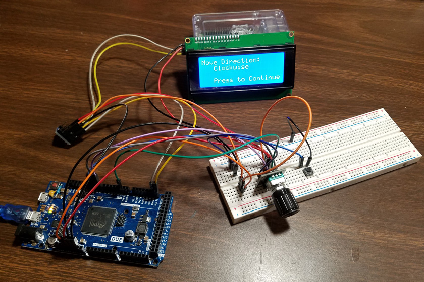
The first breadboard setup included the Arduino DUE , my breadboarding panel including the rotary encoder and a push button, a level shifter
to safely allow mixing 3.3 volt logic (Arduino DUE) and 5 volt logic (display), and of course the display itself. The display is capable of
showing 4 lines of 20 characters each. Currently this all runs from the power of the USB port where the processor board is connected.
After getting everything working, I discovered the display will run on 3.3 volt logic and eliminated the level shifter. I later added the driver
and the stepper motor when they arrived.
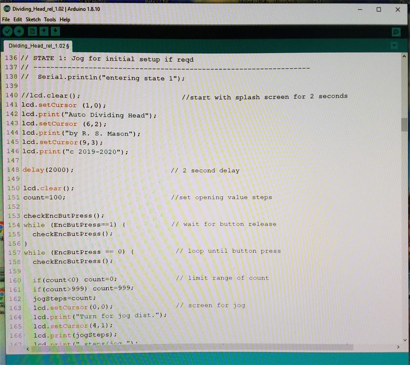
The Integrated Development Environment (IDE) on my computer allows writing and editing the source code, compiling the human readable words to
computer code, and uploading the result to the Arduino. Once the code is loaded to the Arduino, it is self suficient and no longer needs the computer.
The software was divided into several discrete modules which run one after the other. In essence it is a simple state machine. It will enter into the first state and stay there until the user completes it and then it moves to the next. After completing all the states the process is finished. Pressing the reset button will re-start the process, although the nature of use of this machine will usually mean that the machining is complete and the system will be shut down after one run through the various states. Here is a summary of these states:
State 1, Jogging
Before starting to machine, the exact position of the part may need to be adjusted. If this is the case, the jogging mode will allow any size move to be made, from 1 to 999 steps (.0025 to 2.498 degrees) per press. Each press of the MOVE or REVERSE button will move the number of steps showing on the display. This number defaults to 100 steps per press, but turning the resolver will increase or decrease this number, allowing the user to set a position to within 1 step, which is 1/400 of a degree.
If there is no need to pre-position the part, or the positioning is complete, pressing the encoder knob completes this state.
State 2, Select direction
Usually the direction of movement is not critical, but if it should be, it can be easily set. By default the direction is clockwise, which shows increasing numbers on the machine's degree wheel. Turning the resolver knob to the left or right will change the direction accordingly. Pressing the resolver knob transfers to the next state.
State 3, Select move size
There are several screens for input in this state. Initially the system asks for the number of moves per revolution. Any positive number is acceptable here. When complete, the knob is pressed. If the number of moves was greater than 0, the operation moves to the next state. If the number was 0, it then asks for the number of whole degrees to move and accepts any positive number. Pressing the encoder knob then asks for the decimal portion of the degrees and accepts a value from .00 to .99. Pressing the encoder knob will move to the next state.
Note from later: Originally setting by degrees was offered first. After completion I decided it would make more sense to offer the steps per revolution mode first so I rearranged the order of these inputs. I also removed the upper limit on the number of degrees that can be selected per move, as it served no purpose.
State 4, Executes the move
In this state, the MOVE and REVERSE buttons cause the machine to move the desired amount and direction. Normally the MOVE is the only button needed, unless there is an error and a need to go back.
The calculations for the move amount are all done in floating point numbers (includes decimal fractions). This allows the maximum precision. The final position that is calculated for each move is then rounded to the nearest step. The actual step count of the starting position is then subtracted from the desired position and the motor moved the required number of steps. Doing it this way prevents tiny rounding errors in each move from adding up to a larger error. There is a minor amount of backlash in the machine, so when moving in reverse it overshoots a small amount, then returns the amount of the overshoot. This eliminates the effects of backlash by always approaching from the same direction.
This has been an over simplification of the software effort. Not being a programmer, it took quite a bit of time looking up exact syntax required, writing and re-writing code, and troubleshooting. It helped that I was able to concentrate on a single module at a time and confirm its correctness before moving on. During the software writing my stepper motor and driver module arrived and I was able to expand my breadboard to include them.
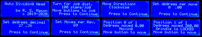
These are the various screens displayed during the operation of the Automated Dividing Head. Numbered from left to right, top to bottom:
#1 is my vanity
splash screen, displayed for 2 seconds at the start
#2 is the Jog screen. The encoder and the buttons are both active. You can vary the step size between making moves.
#3 defaults to clockwise rotation. Turning the encoder left or right selects the corresponding direction
#4 is for setting the whole degree portion from 0 to 360
#5 sets the decimal portion from .00 to .99
# 6 sets the number of moves if the degrees was 0.00
#7 is the display as the spindle is turning. At the end it displays the move number and the total degrees turned
#8 is the result of trying to move while the spindle is locked. When the spindle is unlocked, the move continues
Note: Since re-ordering the set degrees and the moves / rev. functions, screen #6 should really come before screens 4 and 5.
Enclosure:
I used Fusion 360 to design a 3D printed case and cover. The cover mounts the display unit, the rotary encoder, and 3 push buttons. The base mounts the Arduino, a voltage reducing module to power it, the stepper driver, and the power switch and connectors. The Arduino is mounted against one wall (actually recessed into it) with its 2 micro USB connectors and a power connector accessible from the outside.
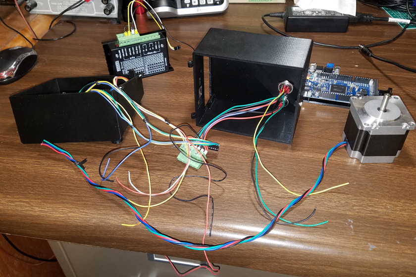
OK, what wire connects to where?
This shows the early stages of assembling the case. The stepper driver is shown in the upper left. It will install
in the rectangular opening that can be seen in the base on the right. This also shows the Arduino and the stepper motor.
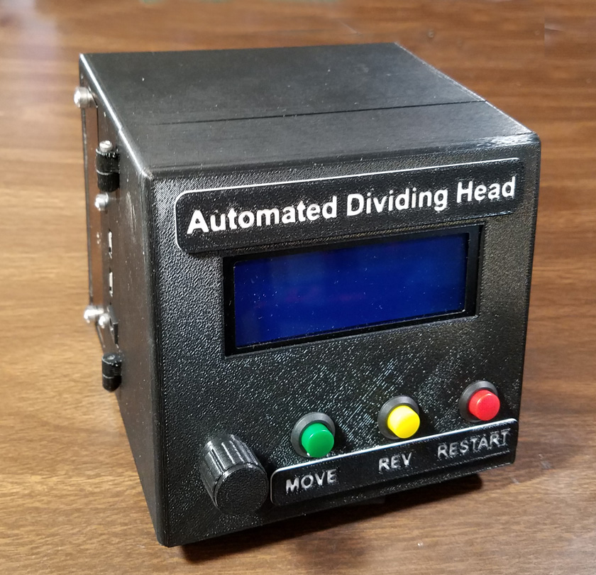
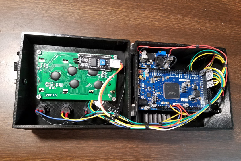
This is the finished case. The left shows the exterior, while the right shows the case open. The stepper driver is mounted behind the Arduino. The system is all powered by
a laptop power supply rated at 19 volts, 4.74 amps. This is plenty to supply the motor and electronics. The Arduino requires from 7 to 12 volts and the small board mounted
at the top of the case is a buck converter, which changes the 19 volts DC to 7.5 volts DC to supply the Arduino, which then has 5 volt and 3.3 volt taps for supplying the
other electronics. The stepper motor driver uses the full 19 volts.
The labels for the case were 3D printed and then attached.
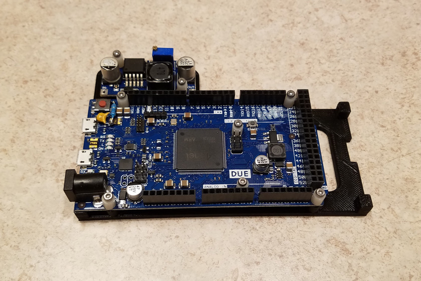
The Arduino and the buck converter are mounted on a printed, removable shelf. Removing this shelf from the case
provides access to the driver module and the connectors.
Mechanics:
Now that I appear to have a properly working control system, it's time to mount the motor and any other accessories needed. I had already decided on a timing belt drive. I looked at available belts and pulleys (they are called pulleys, not sprockets) but found nothing I could afford that had usable center distances. Also, the mounting to the dividing head is a round shaft, flattened on both sides. This would make mounting a standard pulley quite difficult. I already had small pulleys and lengths of belting left over from my CNC project, and I have a 3D printer. Problem solved. I printed a total of 7 pulleys ranging from 80 teeth to 200 teeth. Once I settled on a 90 tooth bottom pulley I discovered that the belt did not quite match the pulley over about an 80 tooth range. At one end it laid into the teeth just fine, but by the other end the teeth had shifted enough that the belt was lifted tooth to tooth. After printing 4 test samples of just the tooth area, I found that reducing the pitch diameter of the pulley 1/2 % gave a perfect fit.
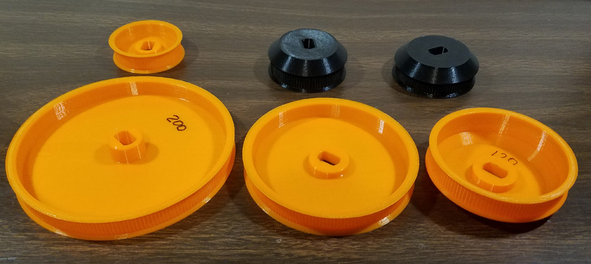
These are the extra pulleys I printed. The orange ones were early in the development, while the black ones are the size and configuration
used on the final version. Note the shape of the mounting on the shaft. These work perfectly!
I spent a lot of time on the mounting of the motor. I initially printed a mount for the motor that attached to the left end of the dividing head. I was planning to run a belt drive horizontally over to the shaft. It then dawned on me that since the entire head can be rotated to set the spindle anywhere from horizontal to vertical, as needed for the machining operation, the center distance of the pulleys would change. This mounting of the motor will not work, as the motor and head must rotate together for the center distance to be constant.
Next I machined an aluminum mount which supported the motor over the top of the unit, and used the same mounting holes as the original index disk. I was planning to splice my own belt to the correct length from a roll of linear belting. It turned out that making this splice in small timing belts is very difficult. I managed to make splices by cutting down the center of a tooth and using super glue to attach them. This provided a moderately strong, fully flexible joint. However, when I tried adding some reinforcement to the outside, the belt became too stiff at the joint to track around the small pulley. I looked, but I could not find ready made belts long enough in the fine pitch I am using.
My final design was to shorten the mount and reverse the mounting of the motor, with the shaft pointing toward the dividing head. Now that the motor could be mounted much lower, and the center distance was much shorter, I was able to buy an assortment of loop belts where the longest 3 were within the range I needed. An Excel spreadsheet with various combinations of pulley size and center distances was made and used to select the best overall combination. I ended up with the following:
I now have a working dividing head, except for a very important safety device - a lockout to prevent
the motor from trying to move while the spindle is locked.
Spindle
lock interlock:
The spindle locking lever rotates to activate the friction type lock. The lever has a ball on the pivot point with a tapered lever extending to a smaller ball on the end. I was stumped as to how to cleanly monitor the lever position and feed it back to the Arduino. In addition, gravity pulled the lever toward the locked position, but lacked the weight to actually make more than a very minor drag.
What I eventually decided was to use an opto-interrupter sensor mounted on the body of the dividing head, and to mount a small flag that would interrupt the beam on the handle.
The opto-interrupter has two short posts with a gap between them. One post contains a small LED and the other side holds a light sensor. The sensor changes its output when something enters the slot and interrupts the beam. I used opto endstops on my CNC machine originally, and actually pirated one of the sensors for this job from one of the no longer used endstops.
I designed and printed a housing to contain the sensor and mount it to the side of the unit. I then designed a snap-on slotted hollow ball to snap over the pivot ball and fit snuggly over the lever. This ball has an arm off one side with a small flat piece to interrupt the beam of the sensor.
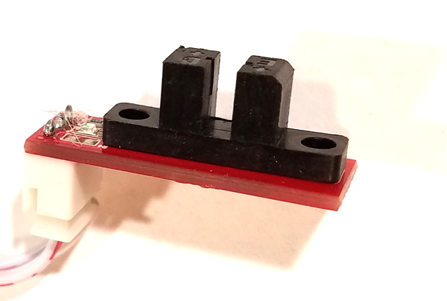
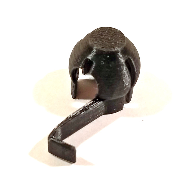
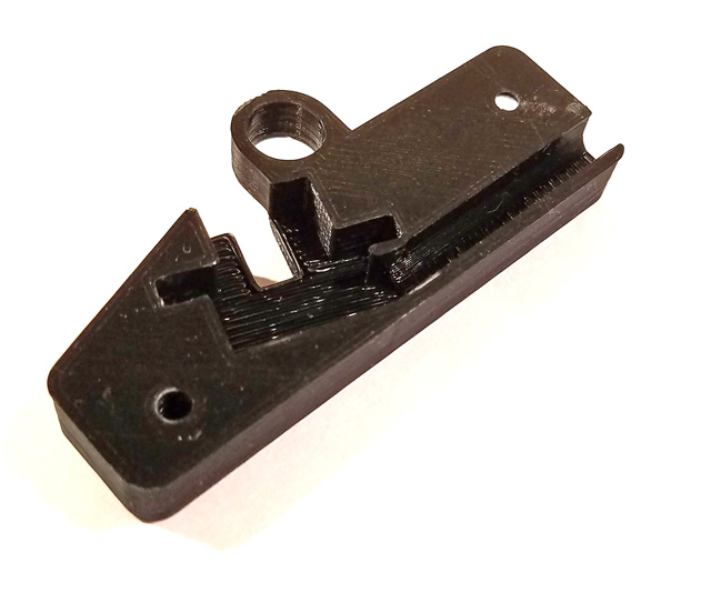
On the left is an endstop like the one I took the opto-interrupter from The center shows the interrupter flag. It snaps on the large ball, fits snugly over the arm and the skirt is very close
to the surface below to keep it all in line. The right shows the rear of the housing. The interrupter fits snuggly in the opening and the wire from it presses tightly into the groove. The large
hole holds a pair of very strong magnets to hold the lever in the unlocked position.
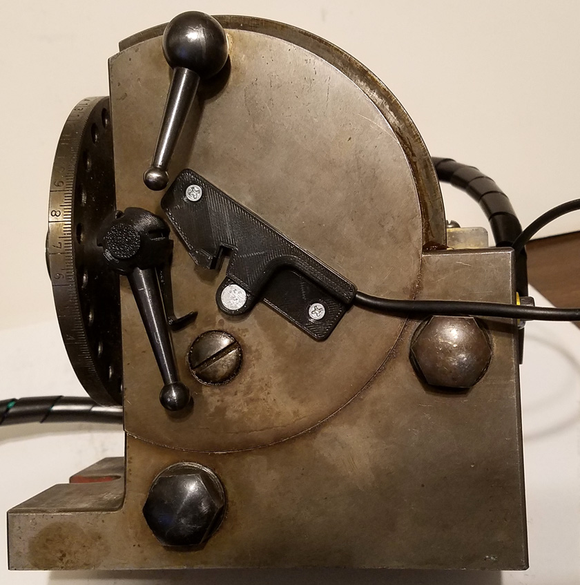
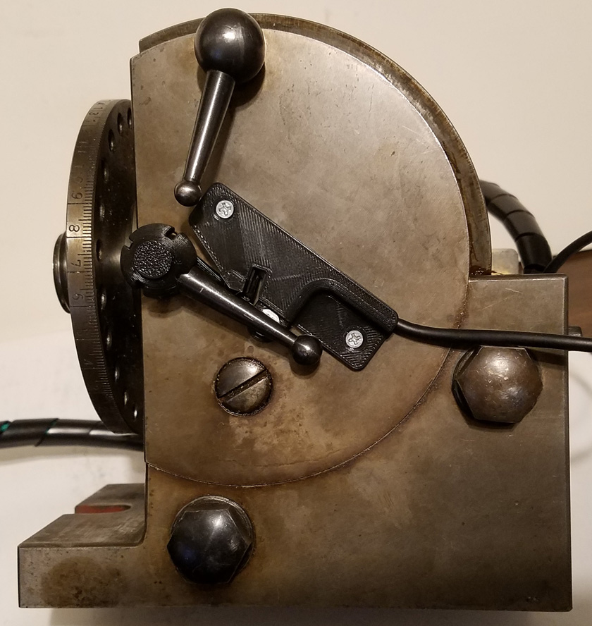
On the left, the spindle is locked (lever down). You can see the flag attached to the lever. On the sensor housing, the round silver object is the end of two very powerful magnets,
stacked one on the other and stuck to the steel on the back. The front clears the lever by about a millimeter (about .040 in.). It is strong enough to securely hold the lever in the unlocked
position and where the flag interrupts the beam without touching anything, as shown on the right. The top lever extends a pin to engage one of the no longer needed "quick index"
holes in the plate to the left. I have not secured it as gravity keeps it from engaging. I probably should lock it down.
After discarding the idea of attaching the housing with adhesive, I decided I should drill and tap two mounting holes. I did not want to drill through the wall, so needed to measure
its thickness. I was able to remove the driving shaft and probe through to the far wall. That indicated the wall was 0.3 inches thick, which was the same as the near wall I could
see directly. I drilled 0.22 inches deep and tapped the holes almost the full depth. That worked perfectly!
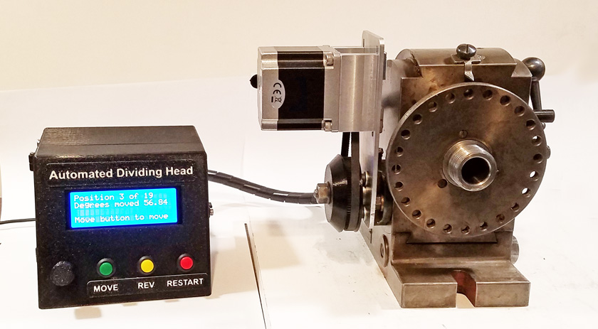
And here is the finished unit minus the chuck, ready to mount on my mill. This is a very heavy unit without the chuck, which is also quite heavy.
I choose to handle the chuck after the dividing head is in place. This is good also as it is almost impossible to bolt this end of the
head to the mill table with the chuck in place!
Now I need to find a project which requires the dividing head! I was going to use it to make a pair of 37 tooth and 47 tooth
gears for my lathe which would allow me to cut metric threads but I 3D printed the gears instead!
Now that I appear to have a properly working control system, it's time to mount the motor and any other accessories needed. I had already decided on a timing belt drive. I looked at available belts and pulleys (they are called pulleys, not sprockets) but found nothing I could afford that had usable center distances. Also, the mounting to the dividing head is a round shaft, flattened on both sides. This would make mounting a standard pulley quite difficult. I already had small pulleys and lengths of belting left over from my CNC project, and I have a 3D printer. Problem solved. I printed a total of 7 pulleys ranging from 80 teeth to 200 teeth. Once I settled on a 90 tooth bottom pulley I discovered that the belt did not quite match the pulley over about an 80 tooth range. At one end it laid into the teeth just fine, but by the other end the teeth had shifted enough that the belt was lifted tooth to tooth. After printing 4 test samples of just the tooth area, I found that reducing the pitch diameter of the pulley 1/2 % gave a perfect fit.
These are the extra pulleys I printed. The orange ones were early in the development, while the black ones are the size and configuration
used on the final version. Note the shape of the mounting on the shaft. These work perfectly!
I spent a lot of time on the mounting of the motor. I initially printed a mount for the motor that attached to the left end of the dividing head. I was planning to run a belt drive horizontally over to the shaft. It then dawned on me that since the entire head can be rotated to set the spindle anywhere from horizontal to vertical, as needed for the machining operation, the center distance of the pulleys would change. This mounting of the motor will not work, as the motor and head must rotate together for the center distance to be constant.
Next I machined an aluminum mount which supported the motor over the top of the unit, and used the same mounting holes as the original index disk. I was planning to splice my own belt to the correct length from a roll of linear belting. It turned out that making this splice in small timing belts is very difficult. I managed to make splices by cutting down the center of a tooth and using super glue to attach them. This provided a moderately strong, fully flexible joint. However, when I tried adding some reinforcement to the outside, the belt became too stiff at the joint to track around the small pulley. I looked, but I could not find ready made belts long enough in the fine pitch I am using.
My final design was to shorten the mount and reverse the mounting of the motor, with the shaft pointing toward the dividing head. Now that the motor could be mounted much lower, and the center distance was much shorter, I was able to buy an assortment of loop belts where the longest 3 were within the range I needed. An Excel spreadsheet with various combinations of pulley size and center distances was made and used to select the best overall combination. I ended up with the following:
teeth on motor pulley
20
teeth on "crank" shaft 90
center distance 82 mm
belt length 280 mm
ratio 4.5 : 1
motor microsteps 4
steps per spindle rotation 144,000
steps per degree 400
teeth on "crank" shaft 90
center distance 82 mm
belt length 280 mm
ratio 4.5 : 1
motor microsteps 4
steps per spindle rotation 144,000
steps per degree 400
I now have a working dividing head, except for a very important safety device - a lockout to prevent
the motor from trying to move while the spindle is locked.
The spindle locking lever rotates to activate the friction type lock. The lever has a ball on the pivot point with a tapered lever extending to a smaller ball on the end. I was stumped as to how to cleanly monitor the lever position and feed it back to the Arduino. In addition, gravity pulled the lever toward the locked position, but lacked the weight to actually make more than a very minor drag.
What I eventually decided was to use an opto-interrupter sensor mounted on the body of the dividing head, and to mount a small flag that would interrupt the beam on the handle.
The opto-interrupter has two short posts with a gap between them. One post contains a small LED and the other side holds a light sensor. The sensor changes its output when something enters the slot and interrupts the beam. I used opto endstops on my CNC machine originally, and actually pirated one of the sensors for this job from one of the no longer used endstops.
I designed and printed a housing to contain the sensor and mount it to the side of the unit. I then designed a snap-on slotted hollow ball to snap over the pivot ball and fit snuggly over the lever. This ball has an arm off one side with a small flat piece to interrupt the beam of the sensor.
On the left is an endstop like the one I took the opto-interrupter from The center shows the interrupter flag. It snaps on the large ball, fits snugly over the arm and the skirt is very close
to the surface below to keep it all in line. The right shows the rear of the housing. The interrupter fits snuggly in the opening and the wire from it presses tightly into the groove. The large
hole holds a pair of very strong magnets to hold the lever in the unlocked position.
On the left, the spindle is locked (lever down). You can see the flag attached to the lever. On the sensor housing, the round silver object is the end of two very powerful magnets,
stacked one on the other and stuck to the steel on the back. The front clears the lever by about a millimeter (about .040 in.). It is strong enough to securely hold the lever in the unlocked
position and where the flag interrupts the beam without touching anything, as shown on the right. The top lever extends a pin to engage one of the no longer needed "quick index"
holes in the plate to the left. I have not secured it as gravity keeps it from engaging. I probably should lock it down.
After discarding the idea of attaching the housing with adhesive, I decided I should drill and tap two mounting holes. I did not want to drill through the wall, so needed to measure
its thickness. I was able to remove the driving shaft and probe through to the far wall. That indicated the wall was 0.3 inches thick, which was the same as the near wall I could
see directly. I drilled 0.22 inches deep and tapped the holes almost the full depth. That worked perfectly!
And here is the finished unit minus the chuck, ready to mount on my mill. This is a very heavy unit without the chuck, which is also quite heavy.
I choose to handle the chuck after the dividing head is in place. This is good also as it is almost impossible to bolt this end of the
head to the mill table with the chuck in place!
Now I need to find a project which requires the dividing head! I was going to use it to make a pair of 37 tooth and 47 tooth
gears for my lathe which would allow me to cut metric threads but I 3D printed the gears instead!
Problems and
solutions
I encountered a couple of problems during the course of this project. The first one was with the power supply. I initially used a power supply from an old Dell computer which supplied 19 volts at a little over 3.5 amps, which was adequate for my setup. For most of the development I merely plugged it in to test, and unplugged it when done and all worked great. After I installed the controller in a case with a switch, when I switched it on, the display lit for about a second, then everything turned off. Plugging it in with the switch already on worked just fine. I reviewed a couple theoretical fixes, but ended up deciding that the supply was just not capable of supplying a sudden load, and had protection circuits to shut it down. My solution was to go to the Habitat For Humanity thrift shop and buy a Sony laptop power supply (for all of $1.00) which provides 19 volts at over 4.7 amps and use that. It now all works fine.
The other problem was a frequent crashing or reseting of the program when I touched the encoder knob. I thought the knob was plastic, but upon closer examination, I found it had an aluminum shell over a plastic inside. I could not see how the aluminum made any contact to the metal encoder shaft, but I did occasionally actually notice a slight spark when I touched it. I had already run a ground wire between the electronics and the dividing head, but the real solution was to design and 3D print an all plastic knob. That has totally eliminated the static problem, except for one time as I reached around the case and touched the metal stepper driver plate. It is easy to avoid doing that, but I doubt it will really be a problem when the unit is bolted to the much larger grounded mass of the milling machine.
Last minute changes:
After reviewing the finished design, I decided that two items needed to be changed. I am just not that happy having the selection by degrees coming before the moves per revolution. In practice, most usage will probably be defined by a given number of equal steps rather than by degrees, therefore it should be the first selection, which will then bypass the degrees input in most cases. So I made the change.
The other item I alluded to above is that I should really provide a way to lock the upper lever from extending a locating pin into the quick index plate. Originally, the quick index function was implemented by loosening two bolts and sliding the crank shaft and worm gear to disengage the gear. The spindle now turned freely and could be positioned every 15 degrees by hand, locking it into position with the indexing pin. With the ease of using the controller for any move, on even numbers or random ones, the quick index function is no longer practical. It would be much harder to use as the motor mounting plate and timing belt pulley cover the bolts that hold the shaft and worm gear in position. To prevent moving the lever, I modified the sensor housing to provide a peg in the path of movement. Now it is impossible to turn that lever and extend the pin.
There is now a post at the end of the sensor housing which prevents the upper lever from extending the pin.
Conclusion:
I am very pleased with the final configuration of the automated dividing head. The controller is small and stand-alone, and includes provisions for all the normal uses, including contingencies which might occur. Every effort was made to keep the accuracy to the very highest level possible.
No external computer is required to feed its input as is the case in some of the YouTube conversion videos. I cannot wait to actually use it in a project!
GO BACK TO "Machine Shop Mods"
R. S. Mason December 2019