Disassembly of a flat screen television and simulated construction of it.
I recently had the opportunity to dissect a nearly new 55 inch flat screen TV which had a damaged screen. I did this out of a personal curiosity about the way such a TV was constructed, and what all it contained. I decided that the report of this project would be more interesting if I reversed the process and showed how it was built, rather than how it was taken apart. This will be a brief report showing the construction of the TV.
The construction starts with a stamped steel plate, the size of the finished TV. This is the basic frame for everything in the TV.
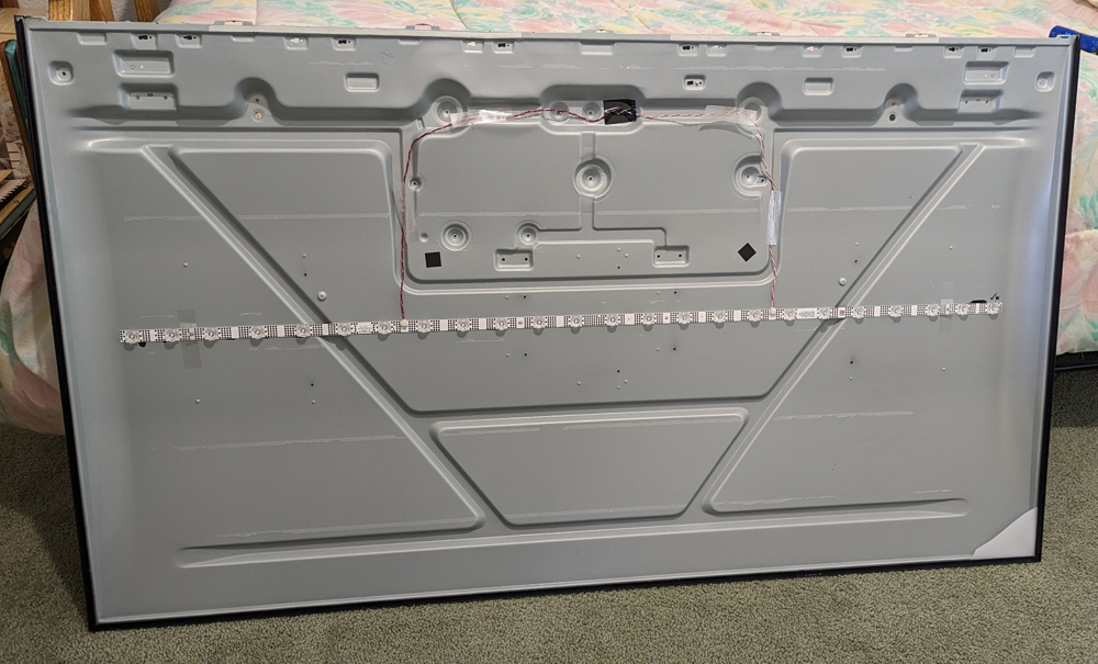
This is the basic frame of the TV, shown here after the LEDs are attached.
Into this frame is glued a thin (1mm or about .04 inch thick) aluminum strip which has a circuit film bonded to it. This strip is pretty much the full width of the frame and located half way up. To this film are attached 24 specially designed LED's which provide all the back lighting for the image. The LEDs are somewhat volcano shaped, which distributes the light much more to the sides than straight up. Then a piece of thin white plastic is glued to the entire frame with clearance holes for the LEDs. This provides a good reflector to spread the light over the entire area of the display.
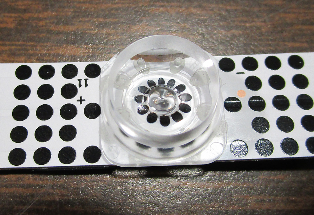
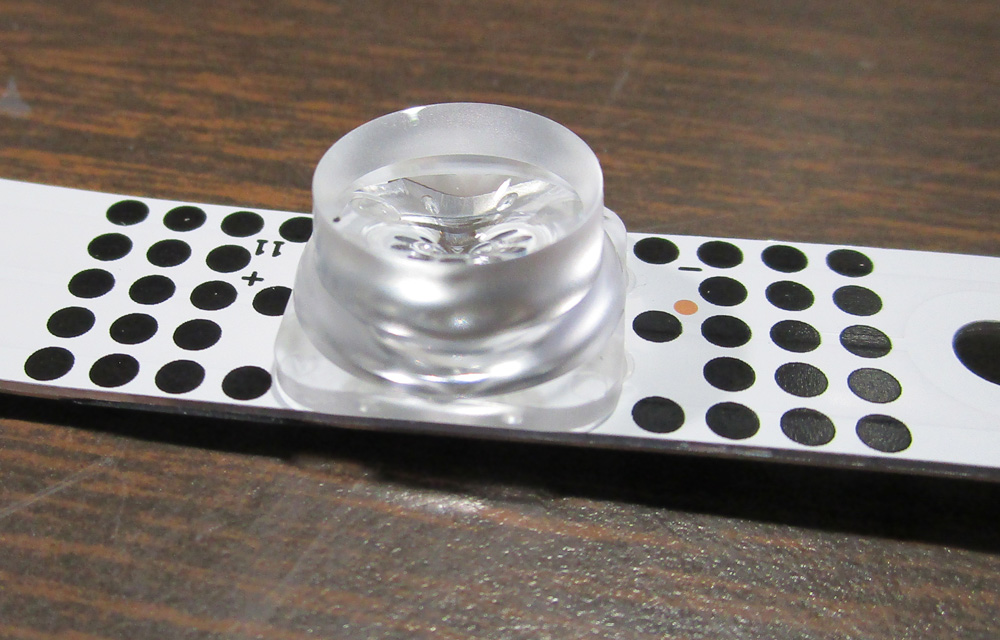
The LEDs are attached to circuitry on an aluminum strip. The unusual shape of the clear lens tends to concentrate the light around the edges, where the light has a longer distance to travel.
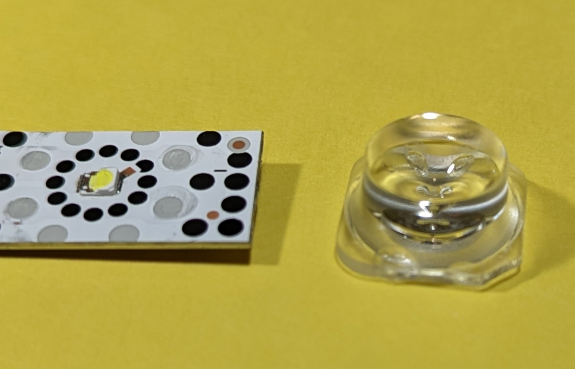
Upon further investigation I found that the LED is a standard COB (chip on board) type, and a special diffusion
lens is glued over it.
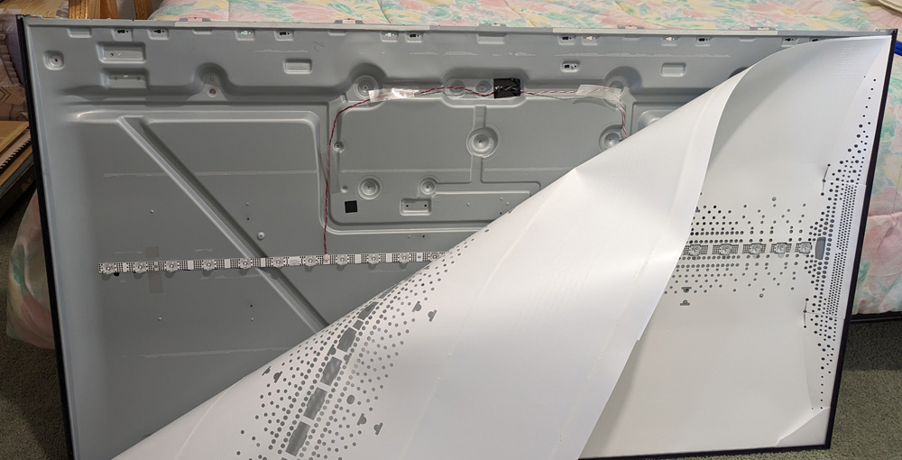
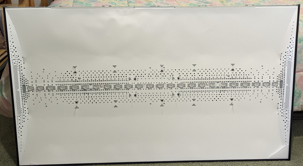
After the LEDs are attached, a white plastic sheet is added around them to provide a good reflector for the light. I assume the patterns of holes are to adjust the reflectivity
to provide a more uniform illumination over the area of the screen.
Next, a panel of translucent white plastic is glued to the frame around the edges, providing a well diffused and quite even source of back light over the full area of the screen. Next is a thin satin looking white layer, which at first I thought to be the first polarizer, but upon examination I think it is a layer to help columnize the light coming from the back light (make all the light beams come straight out of the back light).
Now that the back lighting is provided, the various elements of the display can be added.
___________
How an LCD panel operates:
Let's pause for a moment for a very simplified description of the next few components that make up the LCD display. This display was a 4k display consisting of 3840 horizontal pixels and 2160 vertical ones. This gives a total pixel count for the display of about 8.3 million. However for each pixel there are 3 sub-pixels consisting of red, green, and blue areas to provide the proper color. This gives us a total of about 24.9 million sub-pixels.
In operation, the back light passes through a polarizing filter that eliminates all the light except that which is the same orientation as the polarizer before entering the liquid crystal array, and another which polarizes the light exiting the LCD in the cross orientation. If the LCD does not affect the light passing through it, no light will pass.
In the LCD, the light passes through two very thin sheets of glass (less than 1mm or 0.04 inch) separated by a very thin layer (about 10 microns or .0004 inch) of liquid crystal solution. One of the sheets of glass has an electrically conductive, but transparent coating of indium tin oxide (ITO) printed on it containing a thin film transistor (TFT), a capacitor and a connection defining the sub-pixel area for each of the roughly 25 million sub-pixels. The other glass sheet contains a horizontal line for each row of pixels. Electrical conductors entering the display define each row and each column. Each of the sub-pixels can be addressed by combining the row and column of its location along with a signal for its brightness.
A characteristic of the liquid crystal solution used is that by electrically stimulating it, they can rotate the orientation of the light passing through by any amount from 0 to 90 degrees, thus along with the two polarizing screens, the amount of light can be controlled from 0 to the maximum for each and every sub-pixel.
After passing through the LCD, the light must also pass through a color filter. This sheet has areas of red, green, and blue, separated by a thin black outline, for every one of the pixels, and must be accurately aligned with the pixels on the glass.
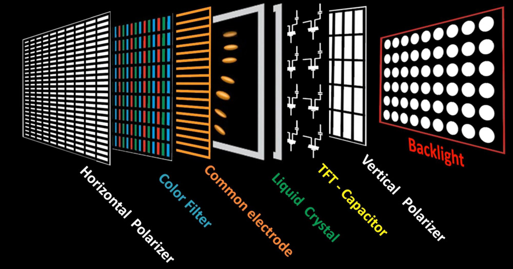
Here is a diagram of the various layers in the LCD module, along with the back light which shines through the stackup.
The orange and yellow layers are the thin glass sheets. Thanks e-learning electronique for the image.
At this point, a viewer can see a high resolution color image on the front of the screen
There are many variations in some of the details of the process described above, but all contain the elements described and usually only vary in the exact type of liquid crystal solution used and sometime the order of the various layers.
And now back to the actual construction:
___________
After the back light components have been installed, the pre-assembled LCD panel is glued in around the edges. This TV is a no-bezel model, so the only part of the TV that extends beyond the display on the top and sides is the thickness of the frame metal.
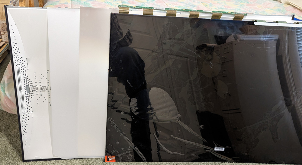
Here we see a spread out representation of the various layers of the display. First, over the reflective LED area is a translucent white
plastic diffuser. Next is a thin columnizer, and finally the sandwich of several layers which is the LCD display. There are
twelve ribbon cables coming from the bottom of the LCD (top as shown here) which transmit all the picture information to the
25 million sub-pixels in the display. All these layers are glued into the frame assembly around the edges.
Now that the display side of the TV is complete, we turn it over to see the rear side.
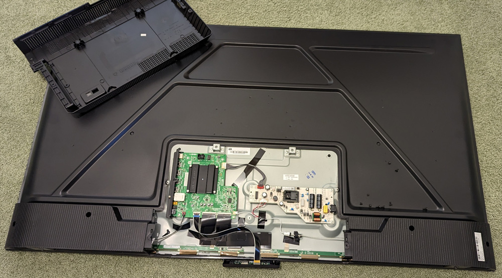
The rear of the TV is mostly the painted rear surface of the main frame. The finished TV has 4 plastic parts over parts of the frame: A large cover
which encloses the electronics boards, two corner covers enclosing the speakers, and a small piece on the bottom which contains the
infrared sensor for the remote, the WiFi module, and the only control button on the TV, which can control power on and off, and
select various inputs.
- The power supply board which converts the incoming AC power into all the DC voltages needed by the other boards.
- The main control board is the TV's brains. All the
channel selection, input, output selections, the streaming channels,
the audio, etc. are controlled by this board. In other words,
everything involved in receiving, controlling, and outputting the
picture and the sound of the TV is handled by this board.
- Two T-con (Timing Control) boards run along the full width at the bottom of the display, and are the interface between the main control board and the LCD display. High level instructions are sent to each of these boards through a ribbon cable from the main control board. The T-con boards process this information and output the specific row and column information to identify each sub-pixel along with its brightness information. Each board connects to the display through 6 smart (there are active IC's and other components on the ribbon film) cables for a total of 12 cables.
- A small board on the bottom of the TV containing the remote sensor, the WiFi module, a control button and an activity light.
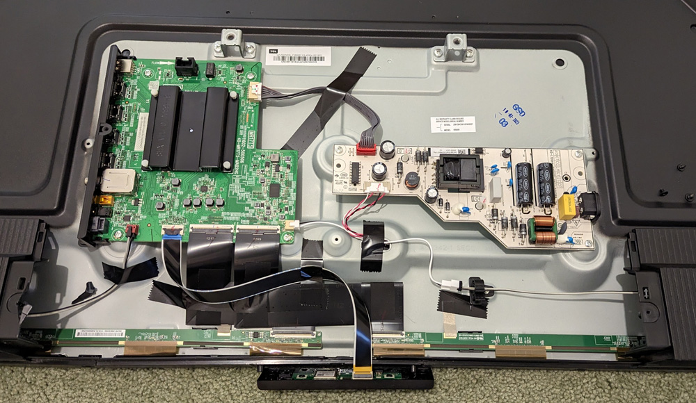
A closer view of the electronics shows the power supply board to the right, the master control board at the upper left, a portion of the 2 T-con boards along the bottom, and the
remote control, etc board on the ribbon cable just below the TV.
Install the covers over the electronics area, the two speakers (already on in the photos) and the remote control/ WiFi board on the bottom edge of the TV and you have a completed TV.
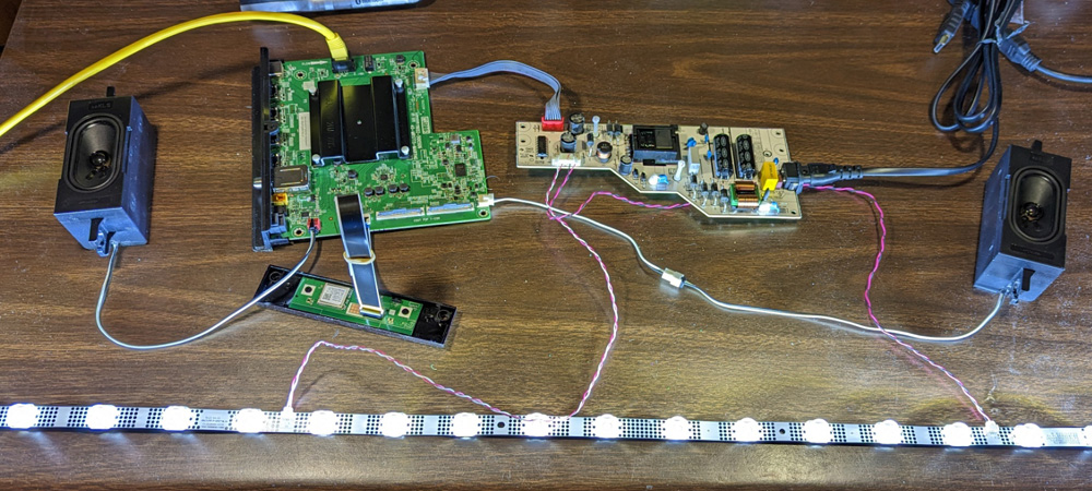
A quick bench test:
After I finished the disassembly of the TV, I decided to try bench testing the boards. I set up the power supply, the main control board, and the remote control/WiFi board on my bench. Since the display is bad I did not try to connect the T-con boards. I did connect the two loudspeakers and the LED strip.
I found that the remote control would turn the TV on and off, and that the volume control would control how loud the pings of pressing the remote keys and the little melody made when turning off the set were, but without a display to prompt me, I was unable to actually tune to a channel and hear the audio on the speakers. I also noted that after turning on the TV, it would pause a number of seconds then turn on the LEDs. After another several seconds, the LEDs would increase in brightness. Turning off the TV would result in the LEDs dimming to off over a couple of seconds.
I don't think there is any practical way for me to actually connect any other type of display to these boards, so I think that is about all I can do with the electronics.
My bench test of the boards showed that they were at least partially operational, but without a display I was merely guessing what
response to give it using the remote control. The only sounds I could get were the beeps of pressing remote keys and a several
tone melody during the turn off process. My hopes of actually tuning in a program and hearing the sound track was not achieved.
GO BACK
R. S. Mason April 2023