A Spot Welder for Making Battery Packs
Background
Over the last several years I have rebuilt several power tool battery packs by replacing the internal cells with new ones. The method factories and quality rebuilders use to connect the various cells together electrically is spot welding a nickel strip to the metal ends of the battery cell. These strips run from cell to cell to connect them as required for the particular tool. The only way I have had to perform this function is to solder wires from cell to cell. This is really not a good technique, as the long duration, high temperatures, and large heated area required cause a considerable rise in temperature within the cell. This can either degrade the cell or outright destroy it in extreme cases A spot welder operates at temperatures well above those of soldering, but for a very short time and heats only a very small area. The total heat rise internal to the cell is actually negligible.
I have recently watched a number of YouTube videos showing a wide variety of home made spot welders built to weld these nickel strips to battery cells. The designs shown vary widely in their complexity and capabilities. The simplest I saw consisted of a car battery with a starter solenoid attached. A pair of wires went to a couple 12 gage wire electrodes which were placed on the nickel strip. The operator then quickly pressed and released a button which activated the solenoid. The timing control was totally dependent on the operator's ability to consistently press the button the correct length of time. Other models had very complex timing circuits driving banks of parallel connected MOSFET transistors to switch the very high currents and low voltages involved.
Something about watching these videos triggered a desire to build a battery spot welder with a simple, economical, but dependable design. I really have no overriding need for one of these machine, although it would be very useful when I do need to build a battery pack. There really were three reasons that I decided to go ahead anyway:
The Arduino is a very small single board micro-controller. It is in reality a small computer designed specifically to easily control a number of analog and digital inputs and outputs. Included is the capability to do logic and numerical mathematical functions and a variety of elaborate control functions. Its programming is based on the C and C++ computer languages and any C programmer (which I am not) should be able to pick up the programming in a few minutes.
My Overall Plan
I decided that using a transformer from a scrap microwave oven, modifying it to remove the high voltage winding and replacing it with a very low number of turns of a heavy welding cable would be the most practical source of low voltage, very high current as needed for spot welding. There are numerous examples of machine using this power source on YouTube. They all appear to have more than enough power and control the welding by suppling a timed pulse or pulses and in some cases even controlling the current output. This would be fairly easy to implement using an Arduino micro-controller driving a solid state relay. This relay would turn the transformer primary on and off as desired, eliminating the need for complex, high current switches which directly control the several hundred amp welding current. I have recently watched a number of YouTube videos showing a wide variety of spot welders designed specifically to weld these nickel strips to battery cells.
This approach would require me to design and build a suitable housing and connection scheme along with the hardware and software to allow the operator to control all the timing setting of the welding pulse(s).
Work is Started
I started looking for a junk microwave oven. The local scrap yard stated that the get them all the time, but that all they currently had were in bales. I wasn't sure if he had said "barrels" or "bales". I shortly discovered that this meant that they were crushed and bound in tight bales about 3 or 4 feet on a side. There was absolutely no way to retrieve anything from there.
I then went to our local Habitat Restore where I found an old microwave for $10. I bought it but really wished that I could have gotten a scrap one. I then did some quick figuring that if the scrap yard charged 50 cents a pound (as they do for steel) it probably would have cost just as much, as I am sure a microwave is at least 20 pounds. I was then happier!
I disassembled the microwave, keeping the transformer and several other pieces. I then tore into the transformer. Fortunately most microwave oven transformers have separate coils for the primary (120 volts) and the secondary (about 2000 volts) which sit side by side on the transformer core instead of being wound over each other in one full length assembly. This allows removing one coil without affecting the other. I removed everything but the primary coil.

To remove the high voltage winding, I sawed one side of the loop of wires flush with the core. I had hoped the rest of the
coil would just pull out from the other side - it did not! I then started pulling groups of strands out until the rest was
loose enough to pull as a unit. There was also a low voltage winding consisting of several turns of an orange wire
which I removed at the same time.
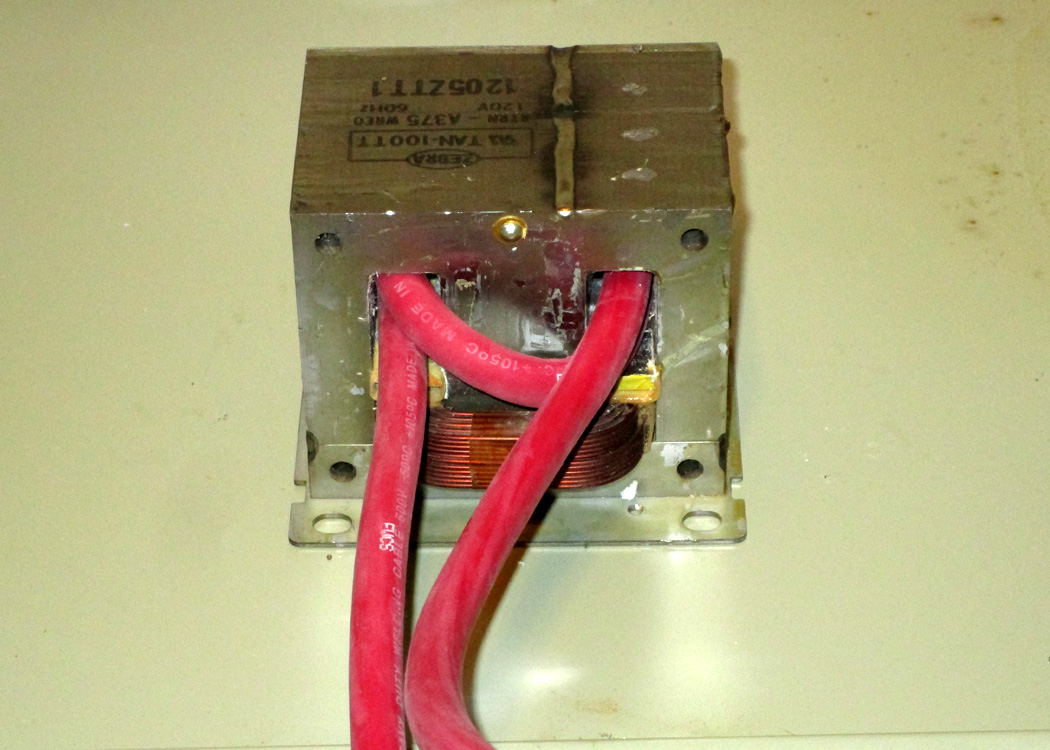
In the space vacated by the high voltage winding, I made a 1 1/2 turn secondary using number 2 gage welding cable.
This provides a secondary of about 2 volts and several hundred amps - ideal for spot welding! The original primary coil
can be seen at the bottom. I was very careful not to damage this when removing the other wires.
On a side note, every video on YouTube I saw that made this modification stated that they used a 2 turn secondary. If
they truly had, the second lead would have exited on the back side. They really had 1 1/2 turns just like this one.
\
In addition I just found a second microwave transformer at a scrap yard. (It turns out that it cost just as much for just a
transformer as scrap as I paid for a total working microwave at a thrift store.) I thought I would share here how I removed
the windings form this transformer. It was much easier and cleaner than my first one. If anyone reading this wants to do
something similar this might help them.
What I did was to cut the high voltage coil with a sharp chisel instead of sawing it. This produced a much smoother cut and
allowed me to drive the coil out of the core with a small block of wood cut to just under the cross section size of the coil.
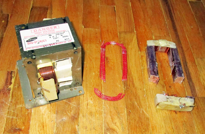
Here is my second transformer (for future use, not this project). After cutting the coil on both sides with a chisel, I was able to
drive the coil out of the core with many, many blows using a small wooden drive tool. Even the 2 1/2 turn 3 volt coil came out fairly
unscathed. I was forced to use this method as the base flange of the transformer did not give me a clear shot at sawing the coil. It
turns out that it was a much better method!
Now that I have my power source I will concentrate on controlling it.
I bought a "starter kit" for Arduino which contained an Arduino micro-controller and many accessories. These included a breadboard and connection wires to make connecting circuits easy, and many sensors, controls, and a display. With this I was able to breadboard test circuits and try out various programs to control them. I started taking YouTube lessons from the same excellent teacher, Paul McWhorter, whose 13 part series on using Fusion 360 I took earlier. He also has a series of lessons on using the Arduino - 36 of them! Using his wonderful tutorials I learned from the starting basics on to some very complex setups using input and output devices of various types. I followed along on each lesson duplicating his setup and trying to solve the problem before he reached the point of telling us how. Several of his lessons used devices I did not have, so I just followed along on those. Pretty soon I had the knowledge to operate an incremental resolver for my user input, an LCD display to follow in making my adjustments and the overall logic to make it all work together.
My welding profile is to fire the system for a short preliminary pulse, wait a short time, then fire a much longer pulse to actually complete the weld. Information I found describing the techniques for this type of welding recommended this approach as the preliminary pulse breaks down any surface dirt or oxidation and provides a good contact between the electrodes and the metal. After a short delay, the main pulse is then more repeatable as the contacts are already solid when it starts. I really don't know how much difference this makes, but with the Arduino it is simple to do, so I did!
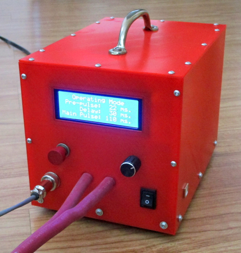
At power on, the display lights up and shows the status of the welder. By default the display shows the settings for the pre-pulse, the delay, and the main pulse and is ready to operate with those parameters. If it is desired to change any of the values, pressing the resolver knob steps through adjusting each of the settings and then back to operational mode. While in the setting mode, turning the resolver slowly will change the settings 1 millisecond at a time. Turning the knob rapidly will change them 10 ms. at a time. After stepping through the 3 setting modes and back to the operational mode, it is ready to weld with the new parameters.
After breadboarding each step of this operation separately, reading the resolver, writing to the display, and writing the code which ties it all together, I put together a breadboard which had all these steps operating together, and finalized my operating code.
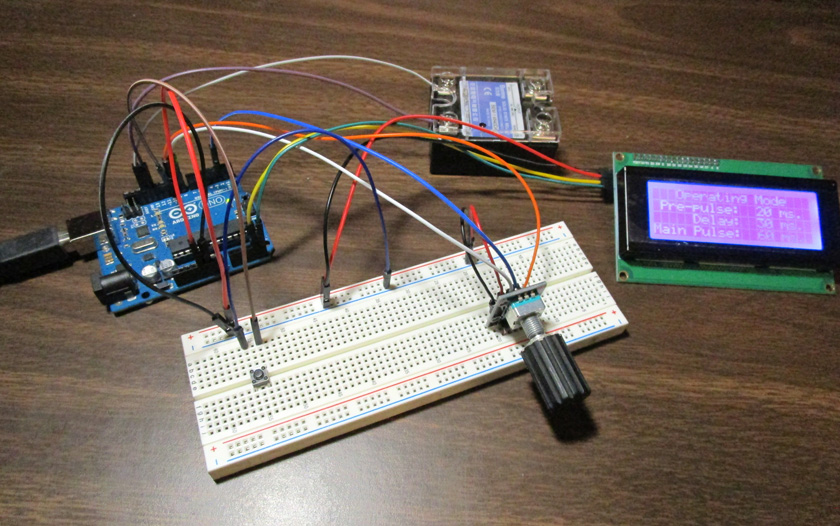
This is my breadboard of the control system. The resolver (with the knob) and the push button send the user input to the Arduino on the left
and it provides output to the display and the solid state relay which will control power to the transformer.
Building the Welder Case
OK, now with a power source and a working controller, I need to build and wire a box to hold all the parts.
I quickly did a rough layout to determine how large a box I needed, then went to my old friend Fusion 360 and started to design it.
I did something I had not done before, I built a multi part assembly shown all together, then I 3D printed each part separately. It worked very well with only one exception. After getting the base, the transformer, and all 4 sides done without a hitch, I started on the top cover. For some reason which I have yet to figure out, I could draw the basic part, but when I tried to extrude the ribs and cut the holes it would not work. I re-did this several time using different methods of defining my working plane and my extrude settings, but with no results. I finally built the part flat on the X-Y plane with everything working as is should. I then moved the completed cover up to its correct position and all was well.
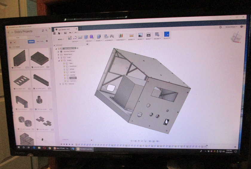
This shot of my computer screen shows the Fusion 360 design. I have turned off the left side panel to show inside. (Actually, I never completed
the left panel as I realized it was identical to the right panel. I later added a cutout for the USB port on only the right cover, but by turning
off the final step, I can still print a left cover.) After completing the design, I was able to select one panel at a time and prepare it for 3D printing.
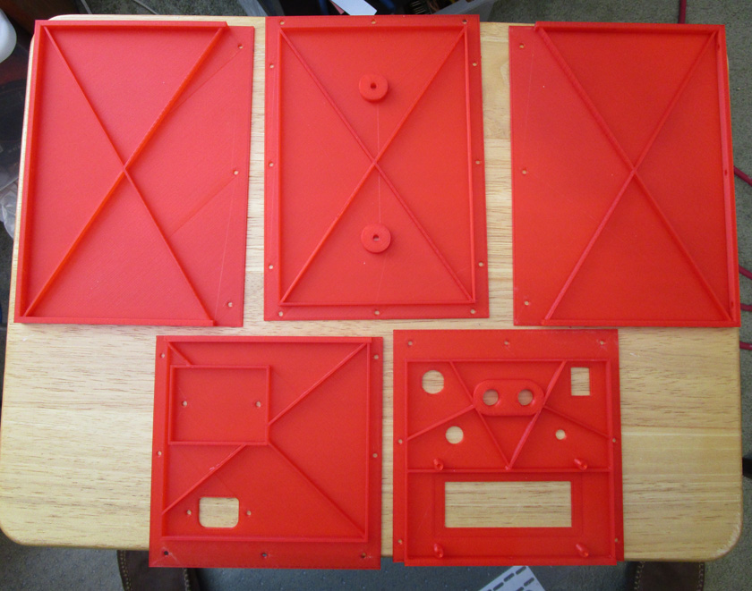
This is the result of printing all the case panels. The ribbing on the plastic panels makes the very thin 1.5mm. plate (about 1/16th inch) very stiff!
The bottom (not shown here) is a panel of just under 3/4 inch thick MDF.
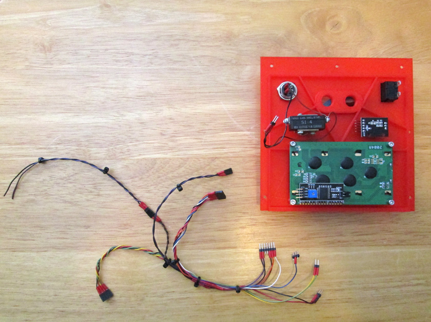
This shows the logic wiring harness; The pin headers on the right all plug into the Arduino, then looking clockwise, the 4 pin header drives the panel display, the
2 loose wires, the solid state relay, the 2 pin header connects to the push button and connector, and the 5 pin header, the resolver.
On the right is the front panel with the connector and push button (upper left), the power switch and resolver (upper right), and the display on the bottom.
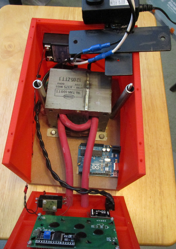
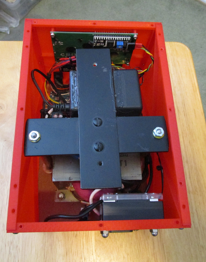
The left image shows the completed AC wiring. It also shows the mounting of the Arduino with the USB port extending through the right hand wall. This will allow any
reprogramming that may be required or desired in the future to be done without any opening of the case.
The right picture shows the completed unit looking from the top-back. Only the top cover and handle are missing here. I wanted a carrying
handle on the top, but I did not want to trust the thin plastic to carry the weight of the heavy transformer. The steel black cross solves that. It is mounted to the base with
pipe standoffs and threaded rod (see left picture). When the top cover is in place the handle screws pass through it and into this assembly. The 12 volt power supply for
the Arduino is mounted to the bottom of this cross.
Over the last several years I have rebuilt several power tool battery packs by replacing the internal cells with new ones. The method factories and quality rebuilders use to connect the various cells together electrically is spot welding a nickel strip to the metal ends of the battery cell. These strips run from cell to cell to connect them as required for the particular tool. The only way I have had to perform this function is to solder wires from cell to cell. This is really not a good technique, as the long duration, high temperatures, and large heated area required cause a considerable rise in temperature within the cell. This can either degrade the cell or outright destroy it in extreme cases A spot welder operates at temperatures well above those of soldering, but for a very short time and heats only a very small area. The total heat rise internal to the cell is actually negligible.
I have recently watched a number of YouTube videos showing a wide variety of home made spot welders built to weld these nickel strips to battery cells. The designs shown vary widely in their complexity and capabilities. The simplest I saw consisted of a car battery with a starter solenoid attached. A pair of wires went to a couple 12 gage wire electrodes which were placed on the nickel strip. The operator then quickly pressed and released a button which activated the solenoid. The timing control was totally dependent on the operator's ability to consistently press the button the correct length of time. Other models had very complex timing circuits driving banks of parallel connected MOSFET transistors to switch the very high currents and low voltages involved.
Something about watching these videos triggered a desire to build a battery spot welder with a simple, economical, but dependable design. I really have no overriding need for one of these machine, although it would be very useful when I do need to build a battery pack. There really were three reasons that I decided to go ahead anyway:
- The machine intrigued me and it would be great when I do need it
- I wanted to design and build a fully featured, high quality machine on a tight budget.
- I wanted to use this as a test case to learn to use Arduino single board computers
The Arduino is a very small single board micro-controller. It is in reality a small computer designed specifically to easily control a number of analog and digital inputs and outputs. Included is the capability to do logic and numerical mathematical functions and a variety of elaborate control functions. Its programming is based on the C and C++ computer languages and any C programmer (which I am not) should be able to pick up the programming in a few minutes.
My Overall Plan
I decided that using a transformer from a scrap microwave oven, modifying it to remove the high voltage winding and replacing it with a very low number of turns of a heavy welding cable would be the most practical source of low voltage, very high current as needed for spot welding. There are numerous examples of machine using this power source on YouTube. They all appear to have more than enough power and control the welding by suppling a timed pulse or pulses and in some cases even controlling the current output. This would be fairly easy to implement using an Arduino micro-controller driving a solid state relay. This relay would turn the transformer primary on and off as desired, eliminating the need for complex, high current switches which directly control the several hundred amp welding current. I have recently watched a number of YouTube videos showing a wide variety of spot welders designed specifically to weld these nickel strips to battery cells.
This approach would require me to design and build a suitable housing and connection scheme along with the hardware and software to allow the operator to control all the timing setting of the welding pulse(s).
Work is Started
I started looking for a junk microwave oven. The local scrap yard stated that the get them all the time, but that all they currently had were in bales. I wasn't sure if he had said "barrels" or "bales". I shortly discovered that this meant that they were crushed and bound in tight bales about 3 or 4 feet on a side. There was absolutely no way to retrieve anything from there.
I then went to our local Habitat Restore where I found an old microwave for $10. I bought it but really wished that I could have gotten a scrap one. I then did some quick figuring that if the scrap yard charged 50 cents a pound (as they do for steel) it probably would have cost just as much, as I am sure a microwave is at least 20 pounds. I was then happier!
I disassembled the microwave, keeping the transformer and several other pieces. I then tore into the transformer. Fortunately most microwave oven transformers have separate coils for the primary (120 volts) and the secondary (about 2000 volts) which sit side by side on the transformer core instead of being wound over each other in one full length assembly. This allows removing one coil without affecting the other. I removed everything but the primary coil.
To remove the high voltage winding, I sawed one side of the loop of wires flush with the core. I had hoped the rest of the
coil would just pull out from the other side - it did not! I then started pulling groups of strands out until the rest was
loose enough to pull as a unit. There was also a low voltage winding consisting of several turns of an orange wire
which I removed at the same time.
In the space vacated by the high voltage winding, I made a 1 1/2 turn secondary using number 2 gage welding cable.
This provides a secondary of about 2 volts and several hundred amps - ideal for spot welding! The original primary coil
can be seen at the bottom. I was very careful not to damage this when removing the other wires.
On a side note, every video on YouTube I saw that made this modification stated that they used a 2 turn secondary. If
they truly had, the second lead would have exited on the back side. They really had 1 1/2 turns just like this one.
\
In addition I just found a second microwave transformer at a scrap yard. (It turns out that it cost just as much for just a
transformer as scrap as I paid for a total working microwave at a thrift store.) I thought I would share here how I removed
the windings form this transformer. It was much easier and cleaner than my first one. If anyone reading this wants to do
something similar this might help them.
What I did was to cut the high voltage coil with a sharp chisel instead of sawing it. This produced a much smoother cut and
allowed me to drive the coil out of the core with a small block of wood cut to just under the cross section size of the coil.
Here is my second transformer (for future use, not this project). After cutting the coil on both sides with a chisel, I was able to
drive the coil out of the core with many, many blows using a small wooden drive tool. Even the 2 1/2 turn 3 volt coil came out fairly
unscathed. I was forced to use this method as the base flange of the transformer did not give me a clear shot at sawing the coil. It
turns out that it was a much better method!
Now that I have my power source I will concentrate on controlling it.
I bought a "starter kit" for Arduino which contained an Arduino micro-controller and many accessories. These included a breadboard and connection wires to make connecting circuits easy, and many sensors, controls, and a display. With this I was able to breadboard test circuits and try out various programs to control them. I started taking YouTube lessons from the same excellent teacher, Paul McWhorter, whose 13 part series on using Fusion 360 I took earlier. He also has a series of lessons on using the Arduino - 36 of them! Using his wonderful tutorials I learned from the starting basics on to some very complex setups using input and output devices of various types. I followed along on each lesson duplicating his setup and trying to solve the problem before he reached the point of telling us how. Several of his lessons used devices I did not have, so I just followed along on those. Pretty soon I had the knowledge to operate an incremental resolver for my user input, an LCD display to follow in making my adjustments and the overall logic to make it all work together.
My welding profile is to fire the system for a short preliminary pulse, wait a short time, then fire a much longer pulse to actually complete the weld. Information I found describing the techniques for this type of welding recommended this approach as the preliminary pulse breaks down any surface dirt or oxidation and provides a good contact between the electrodes and the metal. After a short delay, the main pulse is then more repeatable as the contacts are already solid when it starts. I really don't know how much difference this makes, but with the Arduino it is simple to do, so I did!
At power on, the display lights up and shows the status of the welder. By default the display shows the settings for the pre-pulse, the delay, and the main pulse and is ready to operate with those parameters. If it is desired to change any of the values, pressing the resolver knob steps through adjusting each of the settings and then back to operational mode. While in the setting mode, turning the resolver slowly will change the settings 1 millisecond at a time. Turning the knob rapidly will change them 10 ms. at a time. After stepping through the 3 setting modes and back to the operational mode, it is ready to weld with the new parameters.
After breadboarding each step of this operation separately, reading the resolver, writing to the display, and writing the code which ties it all together, I put together a breadboard which had all these steps operating together, and finalized my operating code.
This is my breadboard of the control system. The resolver (with the knob) and the push button send the user input to the Arduino on the left
and it provides output to the display and the solid state relay which will control power to the transformer.
Building the Welder Case
OK, now with a power source and a working controller, I need to build and wire a box to hold all the parts.
I quickly did a rough layout to determine how large a box I needed, then went to my old friend Fusion 360 and started to design it.
I did something I had not done before, I built a multi part assembly shown all together, then I 3D printed each part separately. It worked very well with only one exception. After getting the base, the transformer, and all 4 sides done without a hitch, I started on the top cover. For some reason which I have yet to figure out, I could draw the basic part, but when I tried to extrude the ribs and cut the holes it would not work. I re-did this several time using different methods of defining my working plane and my extrude settings, but with no results. I finally built the part flat on the X-Y plane with everything working as is should. I then moved the completed cover up to its correct position and all was well.
This shot of my computer screen shows the Fusion 360 design. I have turned off the left side panel to show inside. (Actually, I never completed
the left panel as I realized it was identical to the right panel. I later added a cutout for the USB port on only the right cover, but by turning
off the final step, I can still print a left cover.) After completing the design, I was able to select one panel at a time and prepare it for 3D printing.
This is the result of printing all the case panels. The ribbing on the plastic panels makes the very thin 1.5mm. plate (about 1/16th inch) very stiff!
The bottom (not shown here) is a panel of just under 3/4 inch thick MDF.
This shows the logic wiring harness; The pin headers on the right all plug into the Arduino, then looking clockwise, the 4 pin header drives the panel display, the
2 loose wires, the solid state relay, the 2 pin header connects to the push button and connector, and the 5 pin header, the resolver.
On the right is the front panel with the connector and push button (upper left), the power switch and resolver (upper right), and the display on the bottom.
The left image shows the completed AC wiring. It also shows the mounting of the Arduino with the USB port extending through the right hand wall. This will allow any
reprogramming that may be required or desired in the future to be done without any opening of the case.
The right picture shows the completed unit looking from the top-back. Only the top cover and handle are missing here. I wanted a carrying
handle on the top, but I did not want to trust the thin plastic to carry the weight of the heavy transformer. The steel black cross solves that. It is mounted to the base with
pipe standoffs and threaded rod (see left picture). When the top cover is in place the handle screws pass through it and into this assembly. The 12 volt power supply for
the Arduino is mounted to the bottom of this cross.
In designing the case I had
initially
thought about having my welding probes coming out of the front of the
case and somehow moving up and down to make the weld. Upon
further thought I felt I would be more comfortable welding with a hand
held unit attached to the cables. I therefore have the cables
exiting the case through the front. As I write this portion, I
still have to design and
build the electrode holders to attach to these cables.
Initial tests:
Up until now, I have only tested the power of the transformer trying to weld some fairly thick sheet metal. I was able to get weak welds with materials about 10 times the final thickness I will be doing. This showed me that I have plenty of power to make the types of welds I want.
Finally, my roll of nickel connecting strip arrived and I can try it with realistic materials As I have not yet built (or even designed) my electrode holder, I kludged a setup using a couple of bolts, 2 lengths of 12 gage electrical wire held together with a couple of zip ties, and a piece of cardboard to keep them from shorting out. This worked well enough to determine that the system works very well! My first test on my .15 mm thick nickel (about .006 inch) was to a piece 1/32 inch stainless. This is far thicker than a battery case, but my first attempt stuck the strips together nicely. This was at only 60 ms. and I was readily able to pull the strips apart, however the nickel failed around the weld and left holes where the weld had been. I increased the main pulse to 110 ms. and got a much more substantial weld. When I pulled it apart it left much larger holes around the weld.
I then used a AA battery and welded to it still using 110 ms. and received a beautiful looking weld. I could not pull it apart by hand. I think welds like this are what I want to see each time! I won't do any more testing at this time, as I need to have a suitable electrode holder and electrodes
 .
.
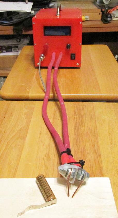
On the left is my test setup showing my cobbled together electrodes and the battery that my final test welded to. I triggered each weld using a foot pedal I
attached to the triggering connector.
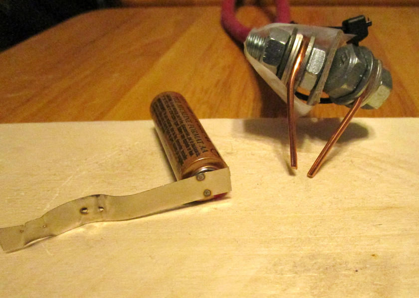
The right shows a close up of the welding test strip and the finely constructed electrode holder. The two small holes on the left of the nickel strip are my first weld. Pulling
it apart left two tiny holes. The center of the strip shows my second test with a longer pulse and larger residual holes after tearing the weld apart. My attempt to weld to
a AA battery was totally successful! I could not pull the strip off the battery with my bare hands and the weld looks very characteristic of factory battery packs.
Operation:
Operating the spot welder is quite simple. The only controls are a power switch, a "weld" push button, a connector for a remote button or pedal, and a control knob. When the system is powered up, it is set to provide default values for a short pulse, a short delay, and a main pulse much longer than the short one. Hopefully I will find that a certain value of each of these will provide consistent, strong welds. Just turning the control knob has no effect unless it is first pressed. Pressing it puts the machine in the mode to adjust the length of the short initial "pre-pulse". Turning the adjustment knob will raise or lower the value of this pulse by one millisecond if the knob is turned slowly, or by ten milliseconds if the knob is turned fast. Pressing the knob again sets the machine to adjust the delay between pulses in the same manner. A third press allows setting the main pulse time, again as above. A forth press of the knob places the machine back in operational mode. There are 5 display screens to indicate the results of these settings.
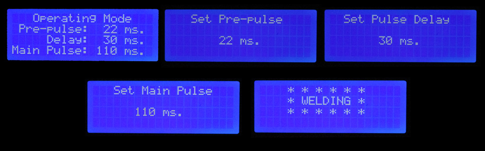
These are the 5 screen displays provided: The first one is the standard operational screen. It displays all the current settings, and is the only screen which allows
a weld to be made. Turning the knob has no effect while in this screen.
The next 3 screens are shown sequentially as knob presses call them up. As the setting knob is turned, the number changes to indicate the new value to be used. Pressing
the knob again after the 3rd setting screen returns it to the first screen.
The final "welding" screen shows momentarily as the weld is actually being made.
Initial tests:
Up until now, I have only tested the power of the transformer trying to weld some fairly thick sheet metal. I was able to get weak welds with materials about 10 times the final thickness I will be doing. This showed me that I have plenty of power to make the types of welds I want.
Finally, my roll of nickel connecting strip arrived and I can try it with realistic materials As I have not yet built (or even designed) my electrode holder, I kludged a setup using a couple of bolts, 2 lengths of 12 gage electrical wire held together with a couple of zip ties, and a piece of cardboard to keep them from shorting out. This worked well enough to determine that the system works very well! My first test on my .15 mm thick nickel (about .006 inch) was to a piece 1/32 inch stainless. This is far thicker than a battery case, but my first attempt stuck the strips together nicely. This was at only 60 ms. and I was readily able to pull the strips apart, however the nickel failed around the weld and left holes where the weld had been. I increased the main pulse to 110 ms. and got a much more substantial weld. When I pulled it apart it left much larger holes around the weld.
I then used a AA battery and welded to it still using 110 ms. and received a beautiful looking weld. I could not pull it apart by hand. I think welds like this are what I want to see each time! I won't do any more testing at this time, as I need to have a suitable electrode holder and electrodes
.On the left is my test setup showing my cobbled together electrodes and the battery that my final test welded to. I triggered each weld using a foot pedal I
attached to the triggering connector.
The right shows a close up of the welding test strip and the finely constructed electrode holder. The two small holes on the left of the nickel strip are my first weld. Pulling
it apart left two tiny holes. The center of the strip shows my second test with a longer pulse and larger residual holes after tearing the weld apart. My attempt to weld to
a AA battery was totally successful! I could not pull the strip off the battery with my bare hands and the weld looks very characteristic of factory battery packs.
Operating the spot welder is quite simple. The only controls are a power switch, a "weld" push button, a connector for a remote button or pedal, and a control knob. When the system is powered up, it is set to provide default values for a short pulse, a short delay, and a main pulse much longer than the short one. Hopefully I will find that a certain value of each of these will provide consistent, strong welds. Just turning the control knob has no effect unless it is first pressed. Pressing it puts the machine in the mode to adjust the length of the short initial "pre-pulse". Turning the adjustment knob will raise or lower the value of this pulse by one millisecond if the knob is turned slowly, or by ten milliseconds if the knob is turned fast. Pressing the knob again sets the machine to adjust the delay between pulses in the same manner. A third press allows setting the main pulse time, again as above. A forth press of the knob places the machine back in operational mode. There are 5 display screens to indicate the results of these settings.
These are the 5 screen displays provided: The first one is the standard operational screen. It displays all the current settings, and is the only screen which allows
a weld to be made. Turning the knob has no effect while in this screen.
The next 3 screens are shown sequentially as knob presses call them up. As the setting knob is turned, the number changes to indicate the new value to be used. Pressing
the knob again after the 3rd setting screen returns it to the first screen.
The final "welding" screen shows momentarily as the weld is actually being made.
The Electrodes:
For the electrode holders, I decided to make a hand held straight line unit - the cables come in the rear and the electrodes come out at the front at nearly right angles. I will have 2 brass bars holding the electrodes at one end and connecting to the power cables at the other. They will be spring loaded downward and pivoting at the rear. This will allow each electrode to adjust its pressure if the holders are not perfectly aligned.
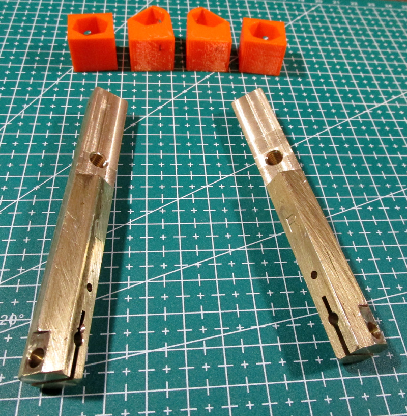
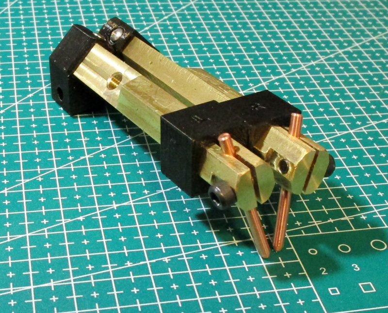
The electrode holders were machined from 1/2 inch hex brass I already had. (Yes, it is nice to still be able to make parts the old fashioned way - by cutting metal!) The flats at the rear are where
I bolt the cable lugs and the hole and slot at the front clamp the electrodes. The holders are mounted using 3D printed blocks which provide insulation, guidance and a pivot point. The orange parts are
prototypes and the black ones are the final version.
The electrodes are angled 15 degrees toward the front and about the same toward each other. The gap is adjusted by changing the length of the protruding electrodes.
As for the electrodes themselves, most YouTube video presenters just use household electrical wire. This seems to work fairly well, but this wire is soft and bends easily. I wanted fairly hard copper so the electrodes would keep their adjustment well. A number of users recommended copper roof nails as an ideal electrode. I got a small box and tried them with mixed results. They are marginally too short, are not very round, and the cross section is rough where the serrations are to make the nail grip well. In the end I bought a couple lengths of precision 1/8 inch diameter hard copper sold as raw material for knife blade pivots.
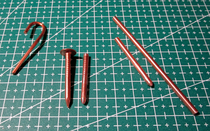
These were my material choices for electrodes: Home wiring #12
gauge wire shown - available in #10 but harder to find, copper roofing
nails, and
precision hard copper rods. Shown also are electrodes made from the nail and the rod.
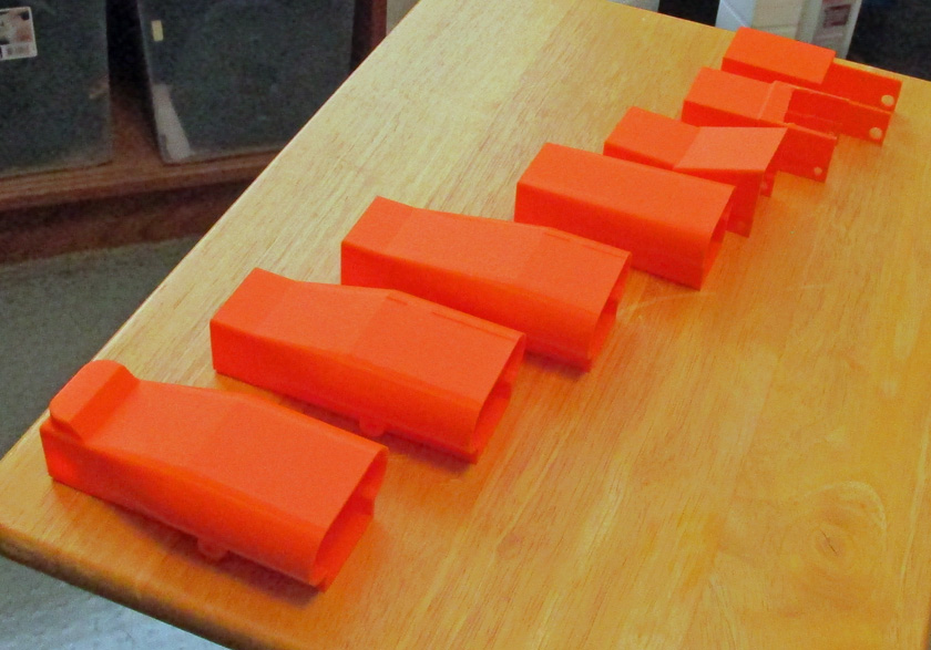
Not having any idea what I wanted for a case or how to make it, I started simple and made many iterations until the case I wanted emerged. The
front prototype needed only a couple minor changes to produce the final black one shown below.
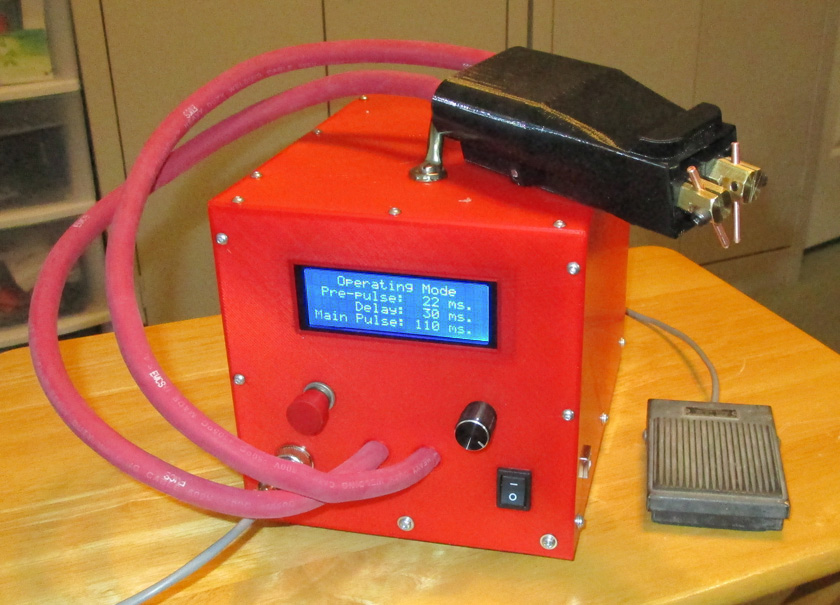
And here is the completed unit!
For the electrode holders, I decided to make a hand held straight line unit - the cables come in the rear and the electrodes come out at the front at nearly right angles. I will have 2 brass bars holding the electrodes at one end and connecting to the power cables at the other. They will be spring loaded downward and pivoting at the rear. This will allow each electrode to adjust its pressure if the holders are not perfectly aligned.
The electrode holders were machined from 1/2 inch hex brass I already had. (Yes, it is nice to still be able to make parts the old fashioned way - by cutting metal!) The flats at the rear are where
I bolt the cable lugs and the hole and slot at the front clamp the electrodes. The holders are mounted using 3D printed blocks which provide insulation, guidance and a pivot point. The orange parts are
prototypes and the black ones are the final version.
The electrodes are angled 15 degrees toward the front and about the same toward each other. The gap is adjusted by changing the length of the protruding electrodes.
As for the electrodes themselves, most YouTube video presenters just use household electrical wire. This seems to work fairly well, but this wire is soft and bends easily. I wanted fairly hard copper so the electrodes would keep their adjustment well. A number of users recommended copper roof nails as an ideal electrode. I got a small box and tried them with mixed results. They are marginally too short, are not very round, and the cross section is rough where the serrations are to make the nail grip well. In the end I bought a couple lengths of precision 1/8 inch diameter hard copper sold as raw material for knife blade pivots.
precision hard copper rods. Shown also are electrodes made from the nail and the rod.
Not having any idea what I wanted for a case or how to make it, I started simple and made many iterations until the case I wanted emerged. The
front prototype needed only a couple minor changes to produce the final black one shown below.
And here is the completed unit!
GO BACK
R. S. Mason February 2019