Creating a Deluxe Shop Oven from an old Toaster Oven
About 6 years ago I decided that I needed a shop oven for occasionally baking, curing, drying, or other wise heating things around the shop. This need increased with the arrival of my first 3D printer where I had filament to dry and desiccant to recharge. At that time I realized that the convection toaster oven in my kitchen would be a wonderful candidate for modifying, but if I did that, I would have to buy a new toaster oven. Instead I went thrift store shopping and found what has to be the ugliest home counter top oven ever made. I rejected it at first, then realized it had everything (except good looks) that I need for a shop oven and bought it for $5. I added a good temperature control, rewired it and ended up with a very serviceable unit. You can see the full story of this conversion by clicking here and scrolling to the bottom of the page.
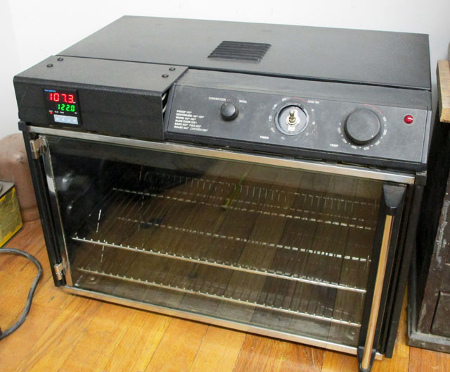
Just for reference, here is my old shop oven.
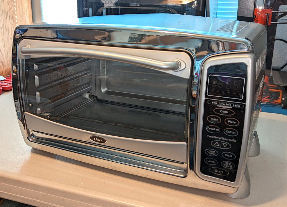
This is the toaster oven I started with. Here, only the rack has been removed prior to starting work.
Design goals:
Before starting any modifications, I needed to define what I wanted in my final oven, and came up with the following:
- The size needs to be adequate for my needs. This was determined by the oven, and I deemed it to be good.
- The temperature range needs to be adjustable from room temperature to 450 degree F.
- The temperature accuracy needs to be within 5 degrees. This was an arbitrary value I selected, but rules out a simple on-off type controller.
- The heating elements need to be fully shielded from the items being heated. Having a line-of-sight to a red hot element would cause radiant heating, possibly well above the set point.
- All switches and controls must fit in the area currently used for controls.
- I desire a reliable timer if it will fit the panel area.
- Assuming a timer, I want to be able to operate in manual mode (on as long as power is on) or through the timer with automatic shutoff at the end of the set time.
- I want to be able to run just the fan or both the fan and heat.
- I want an indicator light that shows when power is actually
applied to the heaters, turning on and off with the temperature
controller cycles.
I started by removing the cover which then exposed the innards of the control compartment. There is quite a bit of room here, but there is a fan to the left of center which could cause space problems. Next I disconnected all the wiring to the control panel and removed the panel. I now had access to all the areas requiring work.
After receiving the temperature controller, but not the timer, I was able to start test fitting everything. The best I was able to tell from the very poorly written timer specs online, was that it was almost exactly the same size as the controller, so I used those dimensions for trial fitting. I 3D printed a number of thin panel layouts to help judge clearances and room for wiring. During the same time period, I generated wiring diagrams that would satisfy my requirements. The location of the fan meant that the temperature controller and the timer had to be at the very top and bottom of the panel. Anywhere else would risk the unit or its wiring hitting the fan.
I was very lucky to find that I had an industrial type panel switch that had the correct configuration of contacts to do my primary power control. I had looked online and was unable to find any reasonable priced units to do that. I had most of the other parts needed. I chose to have a somewhat complex set of switches to assure I could operate in all the modes I wanted.
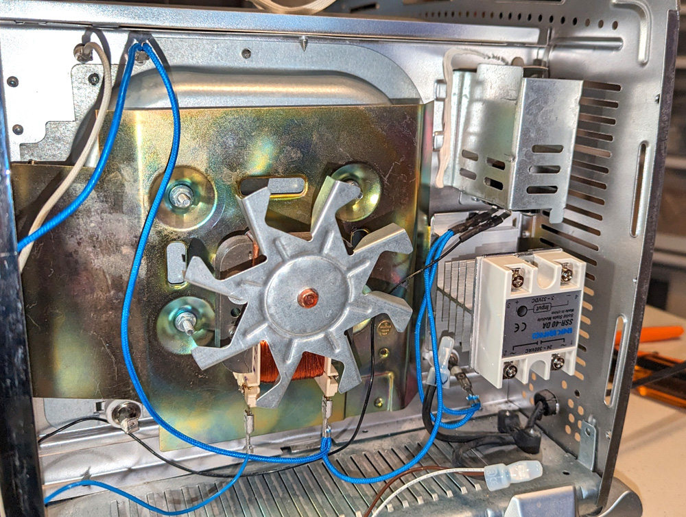
The solid state relay and its heatsink are quite large and the fan mount tab I pointed out earlier
was about the only practical location it would fit. The tab was too narrow to hold the mounting
holes so I screwed a larger plate to it and it held the heatsink.
Now that I am confident that all my parts will fit, and I am still waiting for the timer, I decided I need to get the baffles built and installed over the heater elements. I figured that about two inches in width should shield them adequately and still allow plenty of airflow around them. I went on the home store websites to see what might be available and found that 2 inch roofing drip edge would be about perfect. Home depot did not list them in stock, but Lowes did. I bought an 8 foot length of galvanized drip edge for under $6 and set to it with my tin snips and sheet metal punch. Some pop-rivets and sheet metal screws, along with a lot of time and I had my lower baffles in place. I had to attach these to the side walls, as there is a pull-out "crumb" tray below the elements, and it may still serve a similar service here.
The upper element is basically a square loop, with both ends passing through to the control compartment at one of the corners. This was much simpler! I initially cut most of the bent edge off the drip edge prior to starting construction. I then pre-fabricated a square of the edging, fastening the corners with pop-rivets. The front piece was a little longer to continue over the element ends where they went through the wall. This piece had to be bent downward somewhat as the elements dropped at their ends. Once the square was complete, I attached it to the chamber top with one inch spacers.
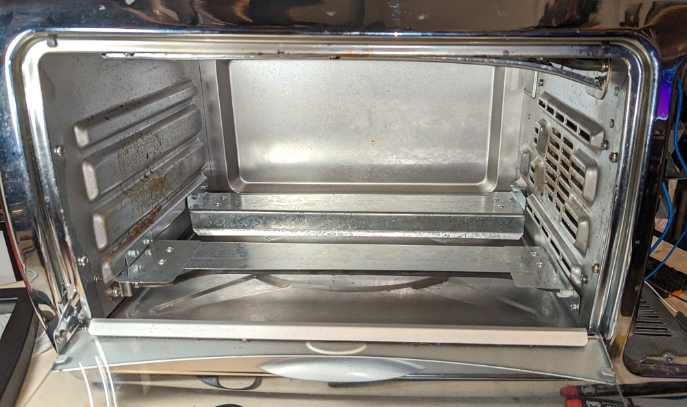
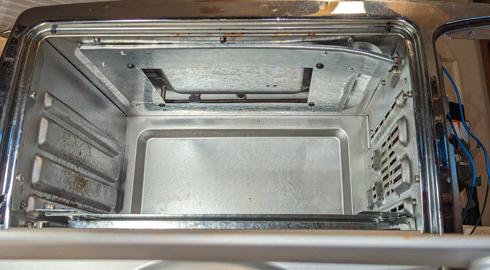
This shows the finished heater baffles. The lower used the drip edge intact. I cut sections from it to make the angle brackets that mount them, and the "wings" at the end to cover the bent section.
I needed to trim most of the angle from the upper material to assure good air flow. The right front corner is wonky (yeah, that's a real word) where I needed to bend it down to clear the angled
ends of the element. Oh well!
I am glad that part is done! It was too cold in my shop, so I did all that sheet metal fabrication sitting in my carpeted office, trying to keep all the little snippets of steel under control and into the waste basket. I was mostly, but not totally successful! I spent a lot of time with a magnet picking up tiny circles from punched holes, tiny rectangles from the nibbler, and little corners (I always snip a small triangular piece off every corner of sheet metal and get a lot fewer scratches and cuts).
Back to the fun part
I had taken many measurements of the original control panel and the mounting area for it and transferred them to a CAD drawing. I then printed out a thin example of the shape and noted where it did not quite fit the original curves. I made a couple minor corrections and ended with a very good fit. I also made several thin panels with various mounting configurations, including one with a long rectangular slot the right width for the two large modules. This allowed me to slide a unit up and down, evaluating the clearance in all positions. The results were as I first assumed; the best places for them were the very top and bottom positions. (Thank you, fan!) I get frustrated with the position of the fan, but without it this project would not exist! The only way to have an even temperature distribution is to have a properly operating fan, in other words, a convection oven!
Once I finalized the locations of all the panel mounted parts, I transformed it into a full thickness version with sides and made my first actual mounting panel. I continued with this through the full wiring process and checked out all the functions. I found that a shortcut I took lighting the heat indicator from the low voltage input of the solid state relay caused the light to indicate even when the master switch was set to fan only. Oh oh! The fix was fairly easy, and I could have just enlarged one hole, replaced a low voltage LED with a 115 volt version and added one wire. However there were valid reasons to reprint the housing and rewire much of it.
Here I am test fitting all the components in the original housing. There is clearance for everything,
but cable management will be critical.
During my wiring, I thought I could get away with using the heat gun to shrink some sleeving in the housing, after all, I used PETG which is higher temperature than the PLA I usually use. I was wrong! In spite of trying to use extreme care, I caused some distortion of the area around the light switch, and even slightly distorted the name plate.
Also, I had added a wire guide to control the exit of the wires from the panel to the oven. This was clamped by the master switch. The plastic washer-like addition reduced friction and allowed the switch to turn in the panel too easily. Of course there was also the new size hole needed for the other lamp, and really the 3 hole cluster should be re-located slightly to better balance their positions.
So, I pulled apart the assembly I had just put together. Actually it was almost trivial. Almost all the wires needing to be disconnected were just clamped under a tiny plate in their specific terminal. Loosen the screw slightly and just pull out the wire, and it could be put back almost as easily.
This allowed me to make several changes to the control housing. First of course was to make the heat indicator hole the larger size for the other light. Along with that I lowered them slightly and moved them sideways for the best visual balance. This also required me to revise the name plate accordingly. There was no change required for the light switch area, other than to not be careless with this one. I also removed the wire guide that clamped under the main switch, and duplicated it as a part of the printed housing itself. I had actually just started printing the new housing when I thought of one more change. The main power switch mounts with a threaded shank just over an inch in diameter. Around this shank are 3 shallow notches through the threads. I revised the printed mounting hole to provide shallow tabs to fit these notches and provide a solid keying with the switch, preventing it from rotating at all in its hole.
The reprinted housing was totally successful and all the minor changes added up to a large improvement. It only took a little over an hour to re-wire it all. There were also improvements in wire routing that became apparent examining the original version.
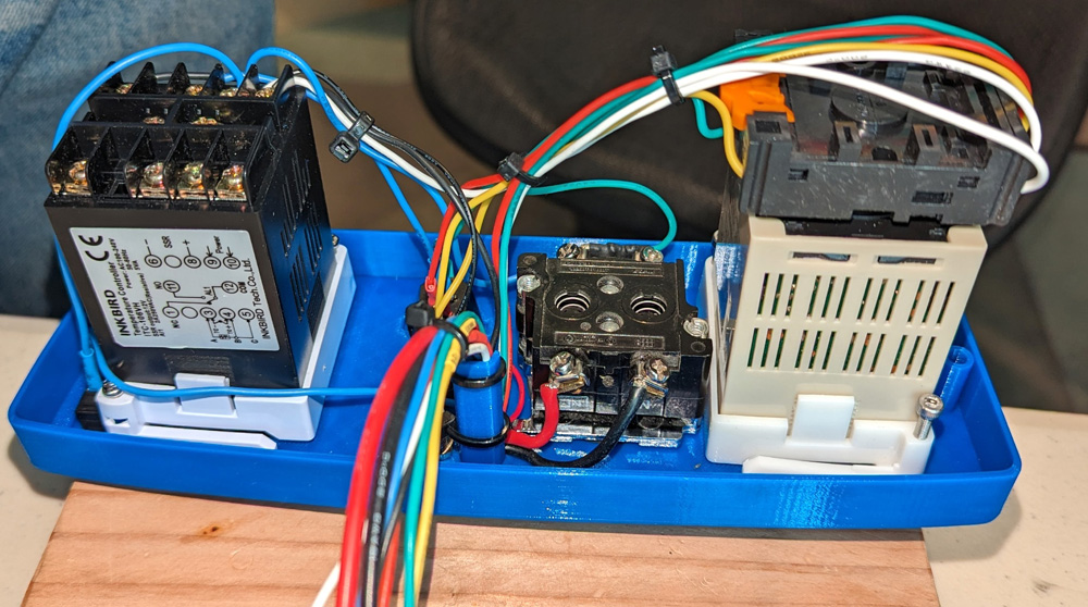
This is the fully re-wired second control panel. On the left (top when installed) is the temperature PID controller, then are 3
components (switch, push button, and the new light), that are totally hidden by the wires. Then is the master power switch and last
is the timer. The wires exiting through the new wire channel are all the connections to the oven except for two spade lugs from
the thermocouple (temperature sensor) which attach to two screws on the temperature controller during installation. There are several
wires carrying 115 volts, but only 2 connecting to the main power switch that carry the full current of the heaters.
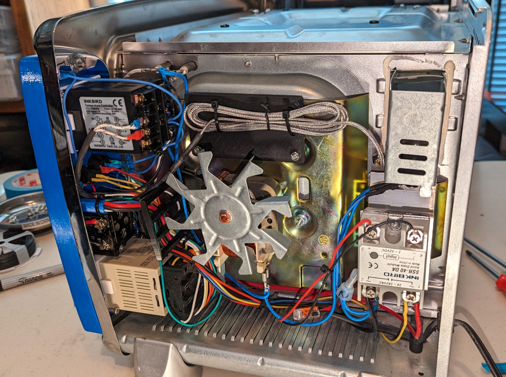
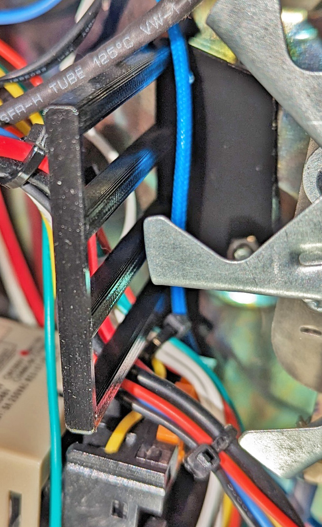
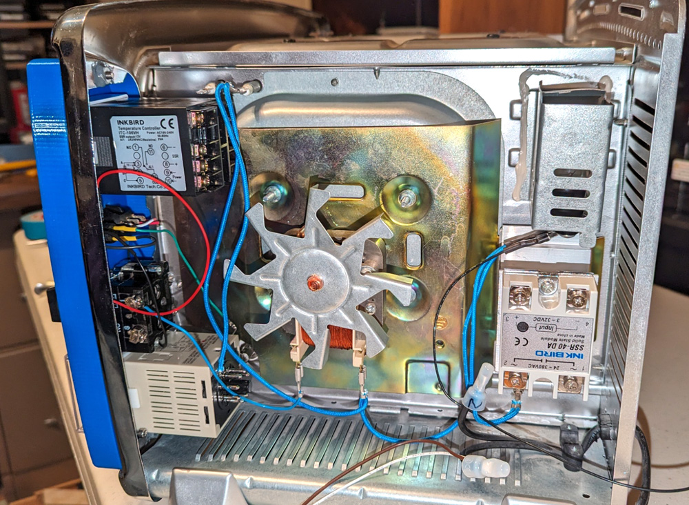
This is the final wiring after installing the control panel. There are 8 wires connecting the control panel to the oven in addition to the two thermocouple
connections (red and blue lugs on the temperature controller, top left). With the fan where it is, cable management is crucial! To keep any wires up front
from getting to the fan blade, I printed a fan guard, barely visible in the left picture, but shown in detail to the right. Remember when I said the long screws
on the fan plate would be important? Well, two of them are used to hold a plate allowing the excess thermocouple wire to be held out of the way, and a
third to hold the fan guard.
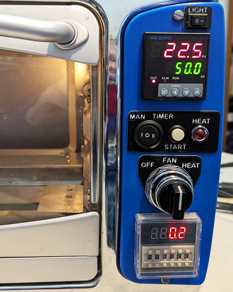
| Here is the control panel in detail: At the very top is the chamber light switch. This was the last control positioned on the panel and there was almost no where it would logically fit. Finally the little corner at the top was selected. Next is the temperature controller. It is currently showing the default factory setting of 50 degrees Celcius. I will be changing it to Fahrenheit. It has a range up to 2399 degrees F, so my measly 450 degrees is no problem. Being a PID type controller, it has excellent control of the temperature, with essentially no overshoot when approaching the desired value. Below that are the mode switch, the push button and the indicator light. The switch selects between manual mode, where the heat will turn on immediately and stay on until you turn it off, and the timer mode where it will turn on only for the time set on the timer. There is a slight anomaly using the timer. It starts its time cycle as soon as the power is turned on, so by the time the oven is up to temperature and you might want to start your timed cycle, the timer will be well into its cycle. That is the functions of the START button. Pressing this will restart the timer. The HEAT indicator turns on whenever there is power on the heaters. As the controller turns the power on and off, the light will track it and turn on and off itself. The main power switch is next. Turning it to OFF removes all power from the oven and everything is fully off. Setting it to FAN powers up all the instruments, turns on the fan, and allows the chamber light to be turned on. It also starts the timer running through its cycle. Setting it to HEAT is exactly like the FAN setting, except that the heater is now allowed to turn on. The final module is the timer. It has many operating modes, but the one I will use just starts running when it gets power or when the start button is pressed. It will then turn on the heat for the set time which can vary between 0.1 seconds and 99 hours. I will probably set it for 2.5 hours for most of my applications. |
 |
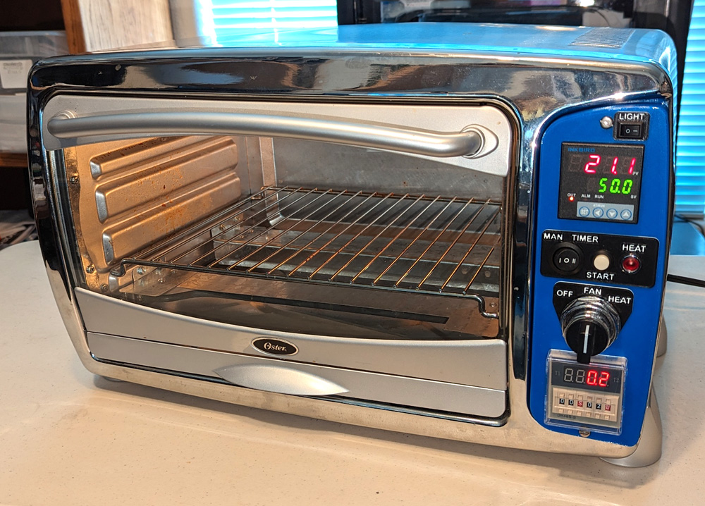
The finished oven is certainly more attractive than my first one, and more capable also. It came out better than I expected!
I started this project primarily to have a project and relieve boredom. I am really happy with the results and now have an oven I will be proud to bring into my house if I so choose! It should be perfect for assuring fully dry 3D printing filament and for recharging the desiccant I use to keep it dry.
It also provided my aging brain with a couple new CAD design challenges, which as my son says, saves money on puzzle books!
GO BACK
R. S. Mason February 2024