Building a Robotic Rubix Cube Solver
A few months later I went back to his website and saw that he had released plans for a newer version which combined all the needed steps into a single operation. I thought that was really a clever device now. A friend of mine, Doug, who also has a 3D printer, and I agreed to jointly each build one, helping each other understand some of the steps required in the construction, wiring, and programming that was needed. The actual construction looked reasonably doable, but modifying and tuning codes written in Python in a Linux environment scared both of us somewhat. But we proceeded to build, tune, and test the robot over a several week period of time.
Mr. Favero called his creation Cubotino. CUBe roBOT ino. The "ino" indicates a diminutive in Italian. It is a small cube robot!
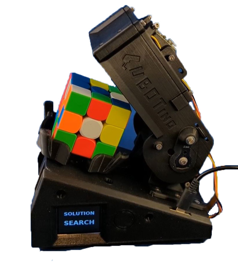
This is Cubotino, a robotic Rubix cube solver.
A brief description of Cubotino:
The Cubotino is a number of 3D printed parts, assembled in a manner to hold a Rubix cube on a cube holder with a cap somewhat like an inverted box, above it. The cube holder can rotate the cube 90 degrees each way, and the box can raise or lower various amounts over the cube, pivoting about the rear.
The cap serves several functions:
In operation the process starts by taking pictures of 4 of the sides, flipping the cube forward between each shot. These initial pictures are merely to set the correct exposure for the camera. Then is retakes those same 4 sides and runs a process which determines the correct color of each of the 9 cubelets on each side. Now the cube holder rotates 90 degrees and flips the cube to photograph one of the remaining sides, flips twice and does the final side. A quick error check is done to verify that 9 cublets of each color have been found and the resulting color patterns are sent to the solving module. This solving routine was developed by a Mr. Kociemba who developed the algorithm for it and then wrote a solver in Python, available for all to use without license. Mr. Favero used the Kociemba solver in this project. The input to the solver is the color pattern of each side, and the output is a list of moves needed to reach the solution. After the 6 sides are photographed and sent to the solver, the rest of the moves are just following the list of moves with no additional feedback from the camera.
Construction steps:
Fortunately for us, the designer did a marvelous job of documenting his creation. His instruction manual was 152 pages long and included an overview of what had to be done followed by very detailed step by step instructions, many photographs and drawings, and detailed instruction of how to connect to an external computer. For this he included each step, usually if a form we could just copy and paste into the robot.
The first 2 things we needed to do were to get all the parts on order and to print all the pieces needed. I pretty much procrastinated until one day I got a call from Doug stating that he had ordered most of the parts and had all the 3d printed parts complete. He then asked how I was doing. Oops! I pulled out all the information and reviewed it, printed all the parts and got back to him. We arranged to get together and finalize the parts orders. Many of the components we needed came in multiple pieces per order so we were able to combine many orders. We finalized all the parts orders and I agreed to build the custom electronics boards for both of us. I am better equipped to do that.
The combiner board is built on perf-board and provides the proper connectors and interconnection for the peripheral parts such as the servos, the display, a touch switch, etc. This board then plugs directly into the main computer, a Raspberry Pi Zero W (or if you can find one to buy, the Raspberry Pi 2W, a newer, faster version). I will frequently refer to this as the RPI.
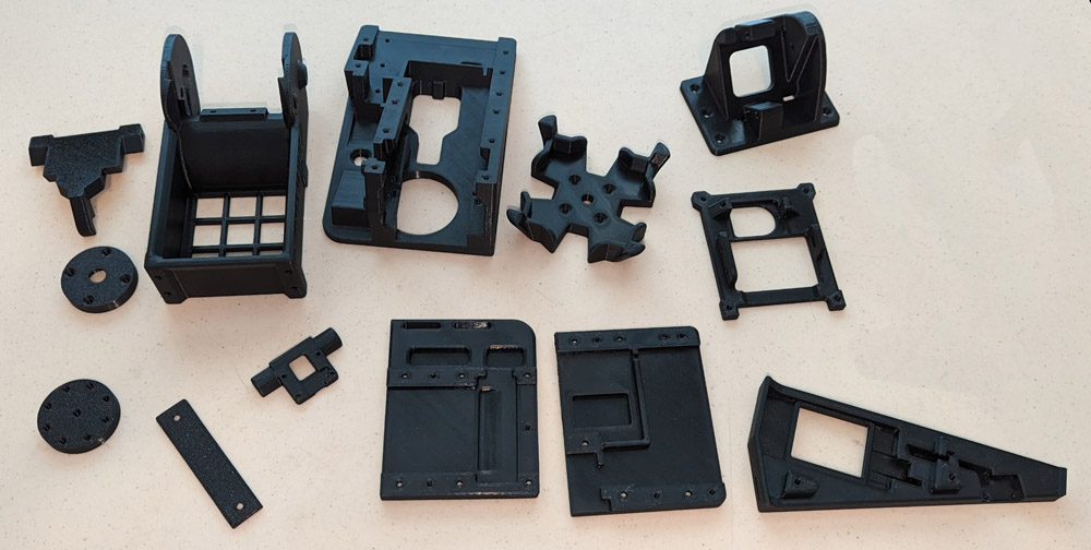
There were a number of parts which needed to be 3d printed. It took the better part of 2 days to print them all.
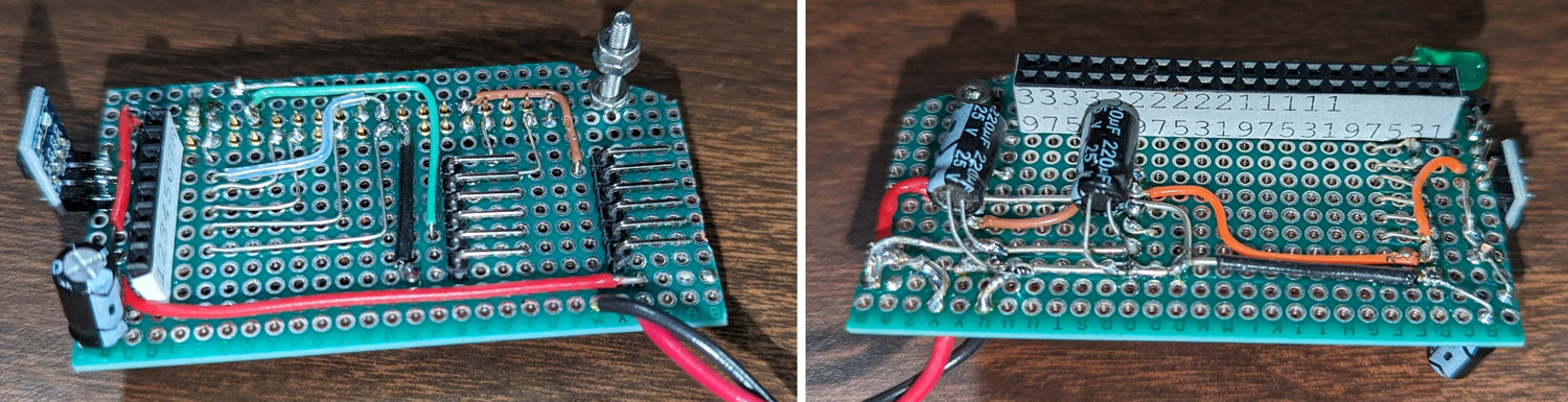
The combiner board was built on a piece of perf-board. The left picture shows the top of the board and shows a connector for the display on the left
and pin connectors on the right for the 2 servos, the LED for lighting the photos, and a touch switch.
The right picture is the bottom of the board and shows the connector that plugs onto the Raspberry Pi computer.
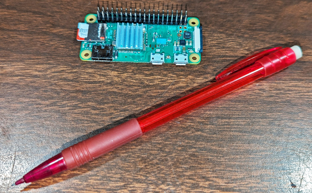
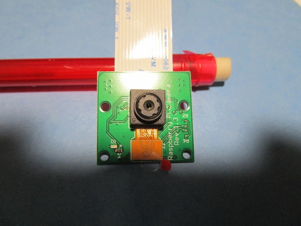
This is the Raspberry Pi Zero W computer. the pencil highlights its tiny size.
After completing the connection boards, most of the parts had arrived, and we started the assembly. The first step was to download the software and firmware needed for the computer. There were several procedures of connecting the RPI to a computer via WiFi and accessing the Linux operating system, the Python program code, and the many data files which held all the parameters which needed to be carefully adjusted for each specific build of the robot.
As we started assembling parts, we would have to pause, connect to the computer, and adjust values so that the cube holder would stop at the exact position specified, and that the cap, which moves up and down would stop at each of 4 different exact positions. As we proceeded with the assembly, we would then need to stop and carefully adjust the camera position and software values to correct the distorted shape of the cube caused by photographing it at an angle, then adjust software masks to show only the exact area of the cube face. It was an interesting experience and really not difficult once we figured out what the designer meant by some of his instructions. We had to try multiple times to get some of his steps to work, but mostly his manual was correct with minimal errors. Sometimes after trying for an hour or so to complete a step, we found that we could repeat it in a minute or two.
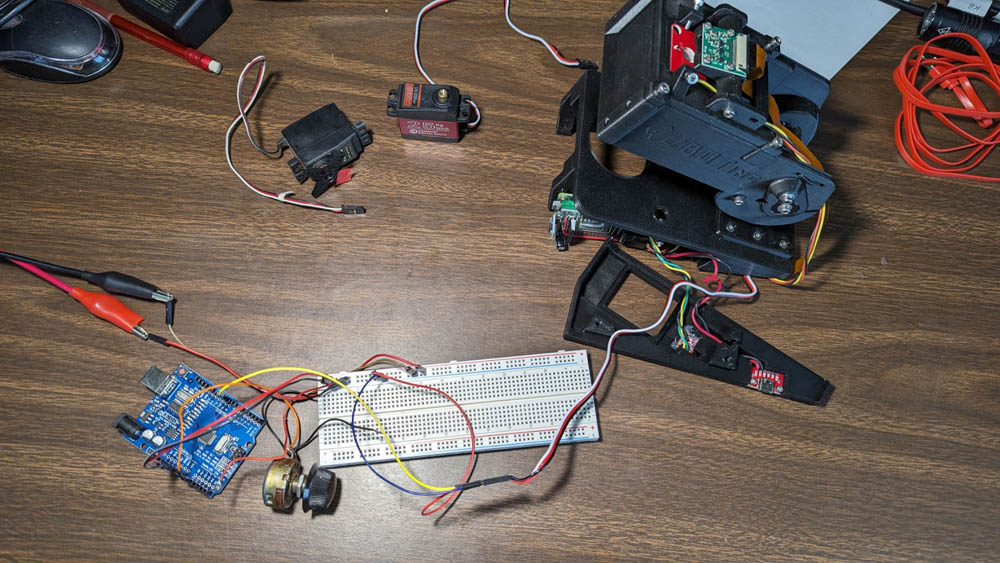
On the left, I set up an Arduino with a simple program to allow easy movement of the servos for initial calibration.
The right shows how tiny the Pi camera is
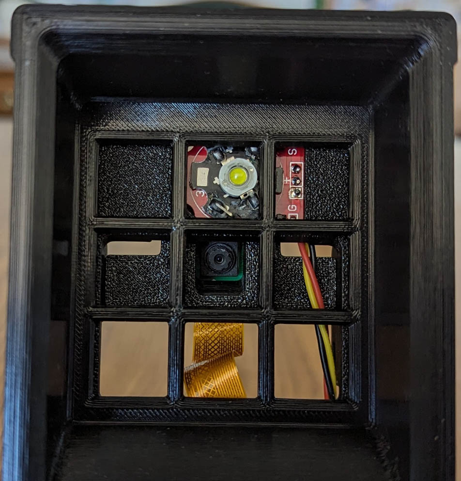
The left shows the LED (top square) which illuminates the cube for photos, and the camera (center square) seen from the bottom of the cap.
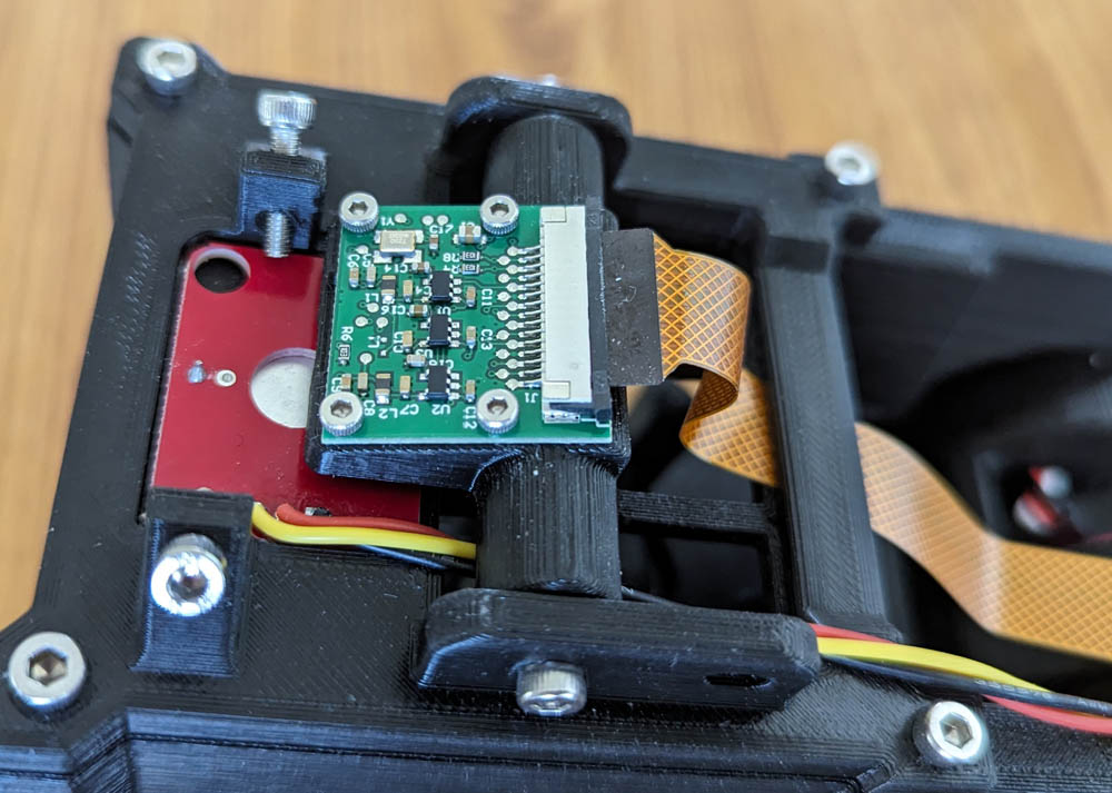
The right shows the LED in red and the Camera in green from the top.

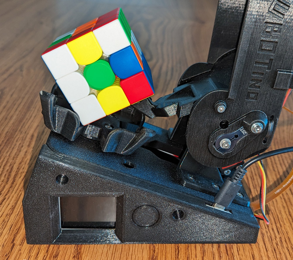
To rotate just one level of the cube, the cap holds the top two sections from moving as the bottom level is rotated.
To flip the cube forward 1/4 turn, there is a "toe" that lifts the rear of the cube when the cap is wide open. This allows the cube to then settle on the next side.
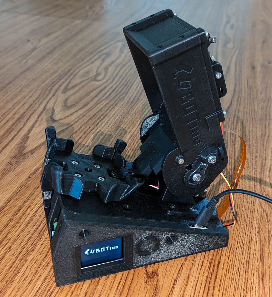
This shows Cubotino from its most photogenic angle. The display keeps track of what is happening
and shows it to the operator. After each side is photographed, it shows a re-creation of the side
with all its colors. It then lists the operation that is currently running, along with a % complete figure. If the
computer ever miss-detects a color, there is an error detected as the total number of each color on all 6 sides
needs to be 9. If not it presents an error message and stop the operation. This happens infrequently,
usually only if there is a bright external light hitting part of the cube.
The circular pattern to the right of the display is the location of a touch sensitive switch behind the panel.
This switch controls the starting, stopping, and shutdown operations. It can also start a special random
"scrambling" mode which prepares the cube for the next demonstration of cube solving.
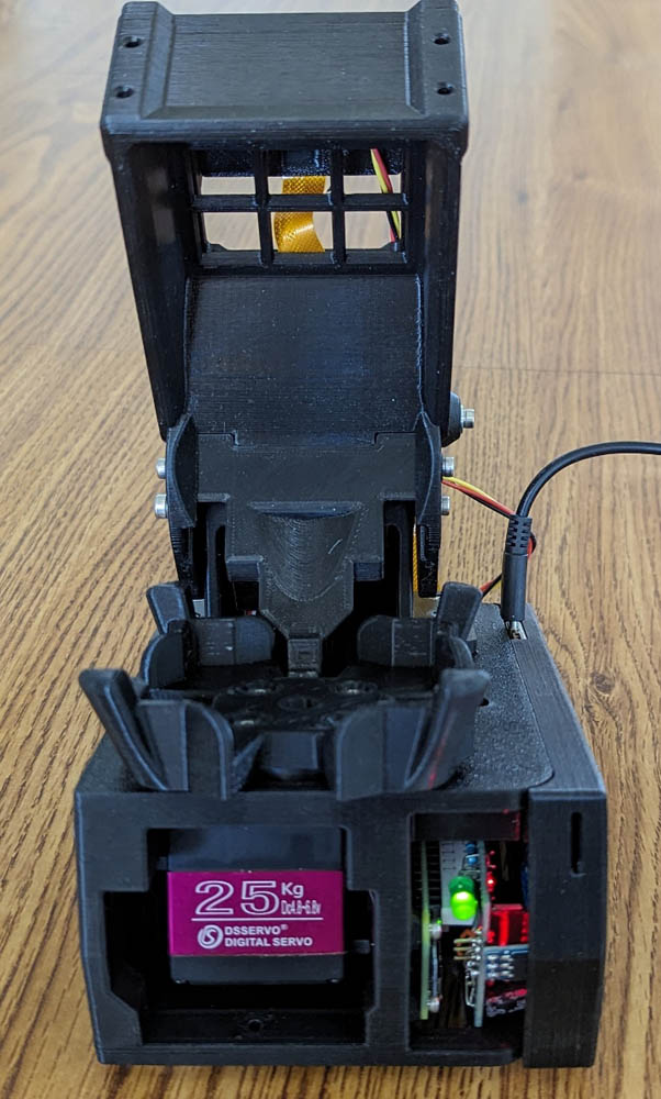
The left view is of the front of the robot. The purple label is on the servo which turns the base. The next opening shows the ends of
the RPI and the connections board.
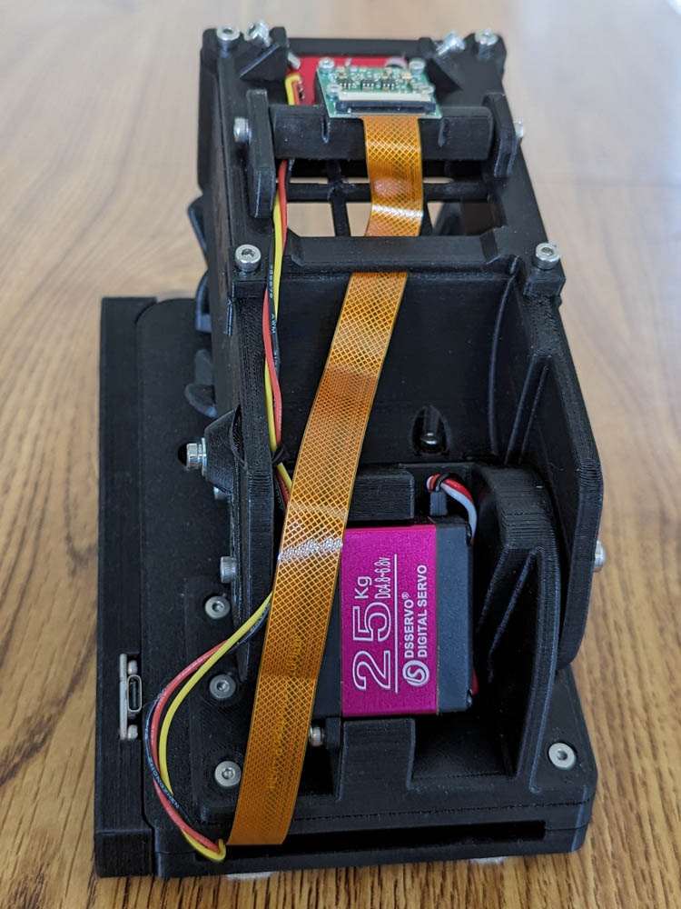
The right view shows the rear of the system. The servo shown here drives the cap up and down as needed.
Links to Cubotino videos:
I took several videos of the Cubotino in action. They are very large files, so I keep them in my OneDrive account, and provide links to access them.
Here are links to Cubotino in action:
Cubotino solving a Rubix Cube.
Cubotino scrambling a cube.
Thanks for visiting! It was a fun project!
The Cubotino is a number of 3D printed parts, assembled in a manner to hold a Rubix cube on a cube holder with a cap somewhat like an inverted box, above it. The cube holder can rotate the cube 90 degrees each way, and the box can raise or lower various amounts over the cube, pivoting about the rear.
The cap serves several functions:
- When the cap is lowered all the way, it keeps the two top layers from turning as the cube holder rotates the bottom layer.
- When the cap is opened just above the cube, the entire cube can be turned.
- When the cap is opened higher, the camera and light in the top can take a picture of the top of the cube.
- When the cap is opened fully, a pawl lifts the rear of the cube, rotating (flipping) it 90 degrees forward.
In operation the process starts by taking pictures of 4 of the sides, flipping the cube forward between each shot. These initial pictures are merely to set the correct exposure for the camera. Then is retakes those same 4 sides and runs a process which determines the correct color of each of the 9 cubelets on each side. Now the cube holder rotates 90 degrees and flips the cube to photograph one of the remaining sides, flips twice and does the final side. A quick error check is done to verify that 9 cublets of each color have been found and the resulting color patterns are sent to the solving module. This solving routine was developed by a Mr. Kociemba who developed the algorithm for it and then wrote a solver in Python, available for all to use without license. Mr. Favero used the Kociemba solver in this project. The input to the solver is the color pattern of each side, and the output is a list of moves needed to reach the solution. After the 6 sides are photographed and sent to the solver, the rest of the moves are just following the list of moves with no additional feedback from the camera.
Construction steps:
Fortunately for us, the designer did a marvelous job of documenting his creation. His instruction manual was 152 pages long and included an overview of what had to be done followed by very detailed step by step instructions, many photographs and drawings, and detailed instruction of how to connect to an external computer. For this he included each step, usually if a form we could just copy and paste into the robot.
The first 2 things we needed to do were to get all the parts on order and to print all the pieces needed. I pretty much procrastinated until one day I got a call from Doug stating that he had ordered most of the parts and had all the 3d printed parts complete. He then asked how I was doing. Oops! I pulled out all the information and reviewed it, printed all the parts and got back to him. We arranged to get together and finalize the parts orders. Many of the components we needed came in multiple pieces per order so we were able to combine many orders. We finalized all the parts orders and I agreed to build the custom electronics boards for both of us. I am better equipped to do that.
The combiner board is built on perf-board and provides the proper connectors and interconnection for the peripheral parts such as the servos, the display, a touch switch, etc. This board then plugs directly into the main computer, a Raspberry Pi Zero W (or if you can find one to buy, the Raspberry Pi 2W, a newer, faster version). I will frequently refer to this as the RPI.
There were a number of parts which needed to be 3d printed. It took the better part of 2 days to print them all.
The combiner board was built on a piece of perf-board. The left picture shows the top of the board and shows a connector for the display on the left
and pin connectors on the right for the 2 servos, the LED for lighting the photos, and a touch switch.
The right picture is the bottom of the board and shows the connector that plugs onto the Raspberry Pi computer.
This is the Raspberry Pi Zero W computer. the pencil highlights its tiny size.
After completing the connection boards, most of the parts had arrived, and we started the assembly. The first step was to download the software and firmware needed for the computer. There were several procedures of connecting the RPI to a computer via WiFi and accessing the Linux operating system, the Python program code, and the many data files which held all the parameters which needed to be carefully adjusted for each specific build of the robot.
As we started assembling parts, we would have to pause, connect to the computer, and adjust values so that the cube holder would stop at the exact position specified, and that the cap, which moves up and down would stop at each of 4 different exact positions. As we proceeded with the assembly, we would then need to stop and carefully adjust the camera position and software values to correct the distorted shape of the cube caused by photographing it at an angle, then adjust software masks to show only the exact area of the cube face. It was an interesting experience and really not difficult once we figured out what the designer meant by some of his instructions. We had to try multiple times to get some of his steps to work, but mostly his manual was correct with minimal errors. Sometimes after trying for an hour or so to complete a step, we found that we could repeat it in a minute or two.
On the left, I set up an Arduino with a simple program to allow easy movement of the servos for initial calibration.
The right shows how tiny the Pi camera is
The left shows the LED (top square) which illuminates the cube for photos, and the camera (center square) seen from the bottom of the cap.
The right shows the LED in red and the Camera in green from the top.
To rotate just one level of the cube, the cap holds the top two sections from moving as the bottom level is rotated.
To flip the cube forward 1/4 turn, there is a "toe" that lifts the rear of the cube when the cap is wide open. This allows the cube to then settle on the next side.
This shows Cubotino from its most photogenic angle. The display keeps track of what is happening
and shows it to the operator. After each side is photographed, it shows a re-creation of the side
with all its colors. It then lists the operation that is currently running, along with a % complete figure. If the
computer ever miss-detects a color, there is an error detected as the total number of each color on all 6 sides
needs to be 9. If not it presents an error message and stop the operation. This happens infrequently,
usually only if there is a bright external light hitting part of the cube.
The circular pattern to the right of the display is the location of a touch sensitive switch behind the panel.
This switch controls the starting, stopping, and shutdown operations. It can also start a special random
"scrambling" mode which prepares the cube for the next demonstration of cube solving.
The left view is of the front of the robot. The purple label is on the servo which turns the base. The next opening shows the ends of
the RPI and the connections board.
The right view shows the rear of the system. The servo shown here drives the cap up and down as needed.
I took several videos of the Cubotino in action. They are very large files, so I keep them in my OneDrive account, and provide links to access them.
Here are links to Cubotino in action:
Cubotino solving a Rubix Cube.
Cubotino scrambling a cube.
Thanks for visiting! It was a fun project!
GO BACK
R. S. Mason September 2023