An Electrical Energy Monitor for my House
November 9, 2021
As an engineer, I like to measure, record, and in general be aware of most things I use and depend upon. My electrical usage is no exception. In recent years, several new residential energy monitors have been developed and have caught my interest. Some of them measure only the main line coming into the house, and then using AI (artificial intelligence) try to figure what is using that current by carefully analyzing the exact characteristics of the electrical load. Others place a sensor on every circuit you want to measure and take separate readings of each line.
My son, who has similar interests reviewed the available products and selected a system from Emporia Energy. This is a system with a small central electronics unit and a number of current transformers (CTs). If a CT is installed around a wire carrying AC current, the amount of current passing through that wire can be read very accurately by the proper electronics. He bought a set with two 200 amp CTs for measuring the main lines entering the circuit breaker box, and 16 50 amp CTs to measure the branch circuits. On a recent visit he brought the kit with him for me to try. I did a quick installation, with all the wires just hanging out of the box with the Emporia electronics hanging from the bottom. I installed an app on my cell phone and another one on my desktop computer. Both displayed a very complete list of the loads on each circuit which can be displayed for different time periods and in either watts or watt hours. My son ended up giving me his unit as an early Christmas present and will buy another for his own use.
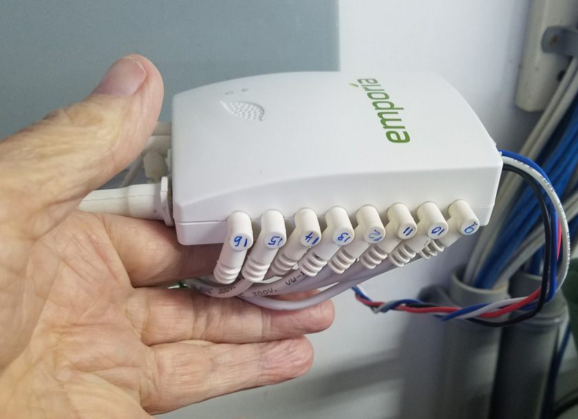
The heart of this system is the Emporia Vue-Generation 2 module. This accepts input from up to 3 total-load inputs (two are typical in residences),
and 16 branch circuit inputs. Each input is from an ampere sensing current transformer (CT). This clamps around a wire and accurately reads
the amount of current in the wire. Each of the readings from these 18 or 19 circuits is transmitted via WiFi thousands of times per second
and can be read on a cell phone, a desktop or laptop computer.
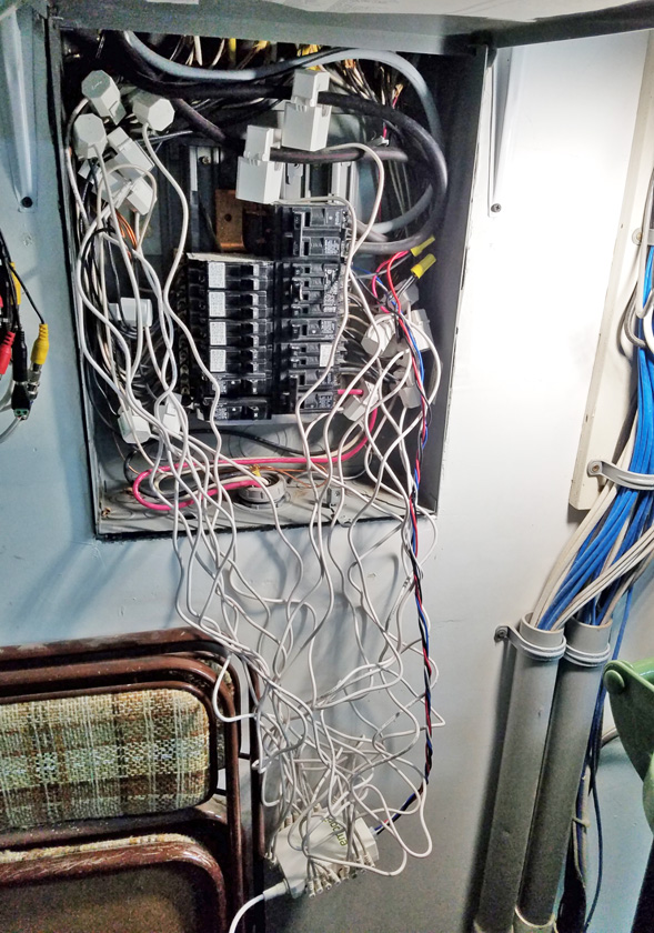
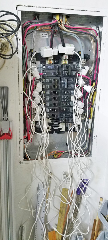
My initial test installation included attaching all the CTs to the various branch circuits in my house circuit breaker panel. From there I just let things hang! All of my
readings were amazing. This thing really works! One of the 18 CTs was defective however and did not show up regardless of where I plugged it in. The company
is sending me a replacement.
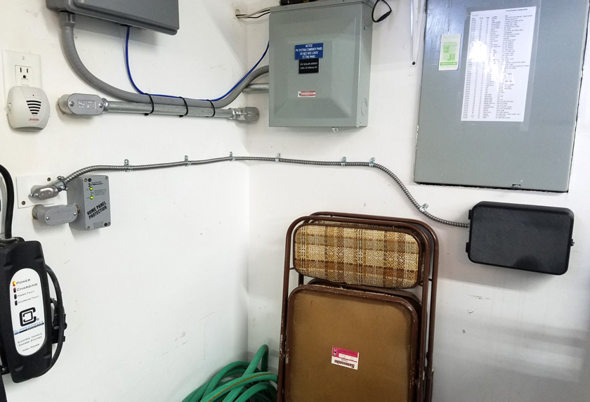
I worked hard to fit everything into the breaker box. I was successful, but I am afraid that the end result would give a heart attack to any electrician who might see this!
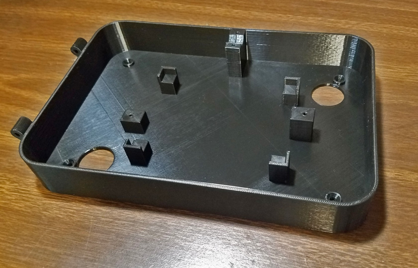
To relieve the wiring jam, I decided to place the main module in a separate box mounted below the panel. I designed and 3D printed this
mounting system. The 4 corner pieces hold the module off the back, the two end pillars hold Z shaped hold-down clips. The WiFi antenna
mounts on the post on the rear wall.
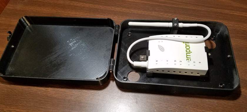
This shows the module mounted into its box.
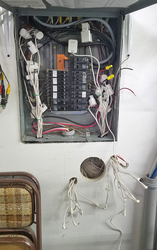
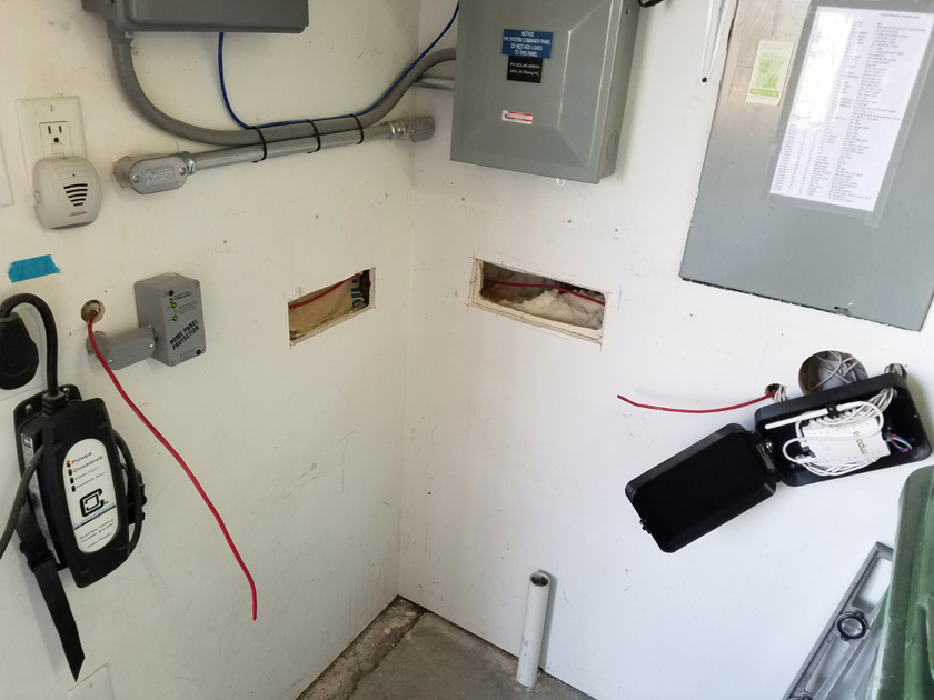
The plan is to have the wires exit the panel into the wall then out the two smaller holes. The large hole is merely for access and will be covered by the box. Excess wire will
be hanging out of sight in the wall. There is also a short length of Romex which carries the 240 volts from the panel to the electronics. Running their standard cord of twisted
wires through a wall would not meet the electrical code.
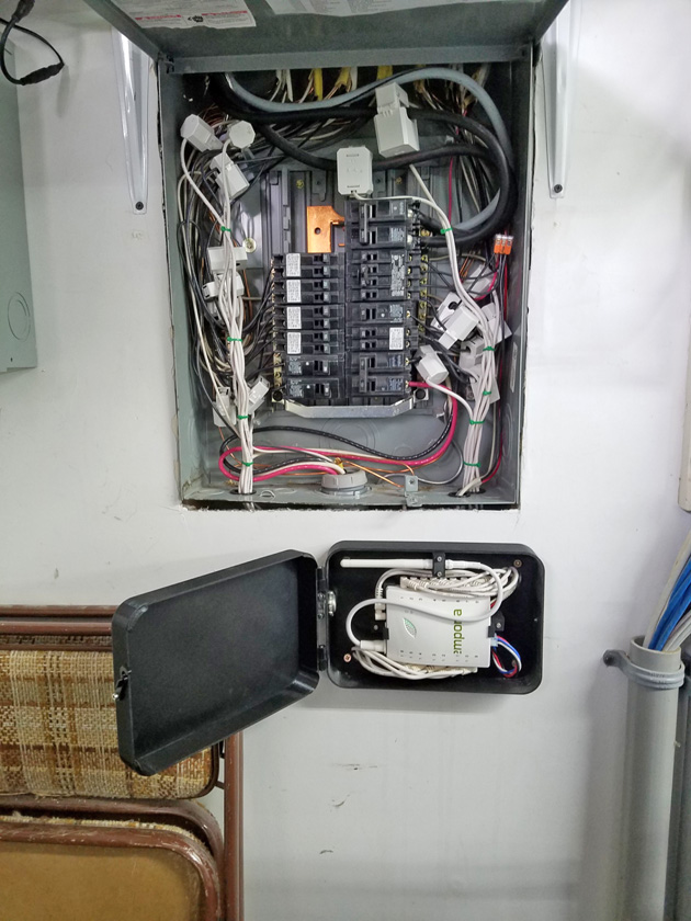
On the right, the wires have been sorted, gathered, and tied together before being sent down into the wall. Only the lengths actually needed to connect to the module are
pulled out of the wall. This results in a much neater installation.
I add one more circuit to the monitor:
In my original overall plan for this monitoring, I was going to need 3 monitoring kits. A full 16 branch circuit one for the house panel, another for the shop one, and an 8 circuit one for the main panel. This main panel was never supposed to exist. It is there because the manufactured home maker delivered the house with a 100 amp panel instead of the 200 amp that I specified. My contractor said that it was no problem, they would simply add a 200 amp panel to the front of the garage to meet my capacity demands. Originally this panel, capable of holding 36 full size breakers, contained only 3 functions. There was a 100 amp feed to the house panel (a double breaker), a 100 amp feed to my shop panel (another double breaker), and a 20 amp feed to a construction outlet in the garage. Several functions have been added since then.
Upon looking further into the details, I realized I could easily do away with the system for the main panel, as there was really only one circuit I was interested in, the charger for my Chevy Volt. The breakers now in this panel are:
I found a post from Emporia on their forum stating that it is OK to extend the wire of a CT up to 30 feet without affecting the accuracy. This allows me to run a connection out to the main panel to pick up that one circuit and make it part of the house monitor. The only difficulty doing this was actually running the wire between the main panel and my monitor.
I almost had to delay adding this circuit, as I was counting on the warranty replaced CT for this circuit. Upon calling the company for the status of the new part, I found it had not even been shipped yet, due to an internal paperwork error. I was not happy! I then looked at the defective one, found how to non-destructively open it up and take it apart. There I found one of the connecting wires was floating in the air, no longer soldered to the CT's internal terminal. I soldered it, carefully re-assembled it, and voila! I have a working CT - with a spare now enroute to me!
In my original overall plan for this monitoring, I was going to need 3 monitoring kits. A full 16 branch circuit one for the house panel, another for the shop one, and an 8 circuit one for the main panel. This main panel was never supposed to exist. It is there because the manufactured home maker delivered the house with a 100 amp panel instead of the 200 amp that I specified. My contractor said that it was no problem, they would simply add a 200 amp panel to the front of the garage to meet my capacity demands. Originally this panel, capable of holding 36 full size breakers, contained only 3 functions. There was a 100 amp feed to the house panel (a double breaker), a 100 amp feed to my shop panel (another double breaker), and a 20 amp feed to a construction outlet in the garage. Several functions have been added since then.
Upon looking further into the details, I realized I could easily do away with the system for the main panel, as there was really only one circuit I was interested in, the charger for my Chevy Volt. The breakers now in this panel are:
Master breakers feeding the house
and shop sub-panels. The monitoring for these are covered by the
systems for those panels.
A single "construction" outlet placed during the building of my garages and shop. I seldom use this outlet.
A pair of breakers to connect my whole house surge suppressor. No current normally flows here.
A pair of breakers to connect my solar system to the grid. My solar has its own monitoring system.
A pair of breakers supplying power to my car charger. This is the one I want to include!
I found a post from Emporia on their forum stating that it is OK to extend the wire of a CT up to 30 feet without affecting the accuracy. This allows me to run a connection out to the main panel to pick up that one circuit and make it part of the house monitor. The only difficulty doing this was actually running the wire between the main panel and my monitor.
I almost had to delay adding this circuit, as I was counting on the warranty replaced CT for this circuit. Upon calling the company for the status of the new part, I found it had not even been shipped yet, due to an internal paperwork error. I was not happy! I then looked at the defective one, found how to non-destructively open it up and take it apart. There I found one of the connecting wires was floating in the air, no longer soldered to the CT's internal terminal. I soldered it, carefully re-assembled it, and voila! I have a working CT - with a spare now enroute to me!
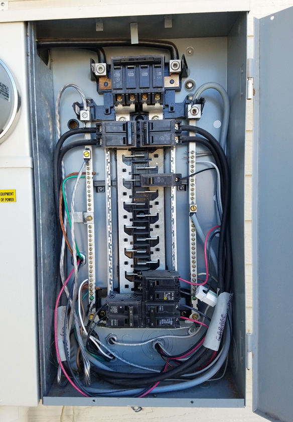
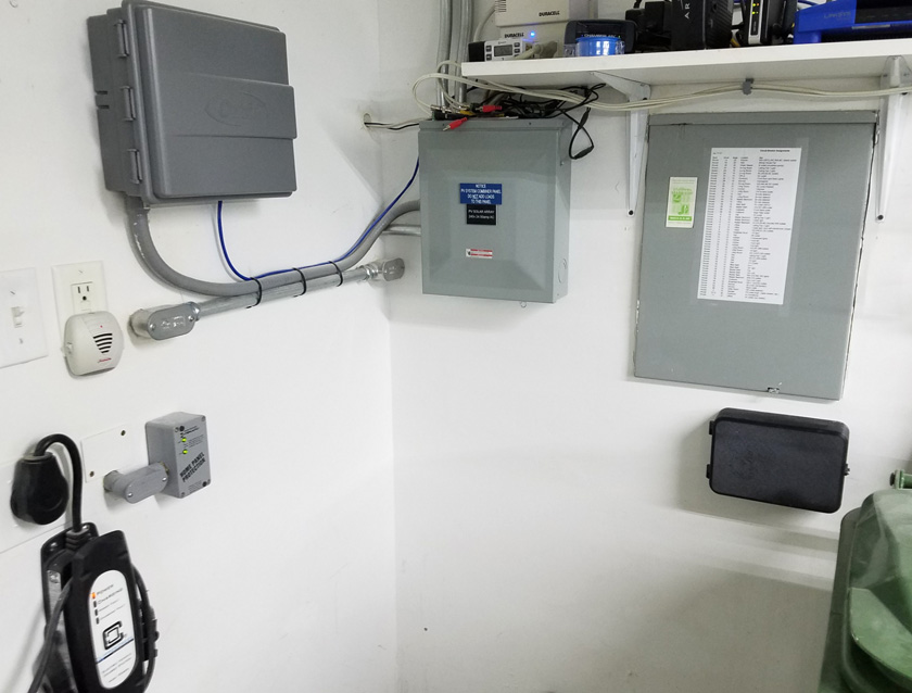
This is my main panel. The charging circuit CT is clamped over one of the car charging wires. Its wire then runs through
yet another passage from inside the panel box, through the wall into the garage.
Inside the garage the wire passes through a right angle fitting to a length of armored cable from which I removed the original 12 ga wires and
replaced them with the extended cable from the CT. This then enters the end of the module box.
I would really like to have placed this wire entirely within the walls, but that would have required me to cut several access holes, to drill through
studs, then to patch and paint the walls. Also I really don't know how I would have gotten around the corner, but if that armored cable bothers me
enough, I might still do that!
This picture shows that now, within a few inches of each other I have interconnections consisting of Cat5 internet cable, watertight
plastic conduit, EMT metal conduit, and now flexible armored cable. I guess I just cannot decide!
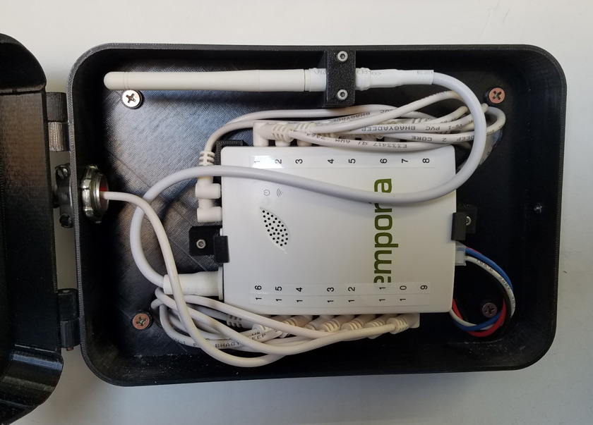
And here is the other end of the CT's wire, connected to the Emporia electronics unit.
OK! So I really don't like it!
It didn't take any time at all before I decided that I really dislike the looks of the armored cable draping its way across the wall! The day after I finished installing it, I got out my oscillating saw and cut two large openings in my walls. I had readily located the studs on the front wall, but the wall that was the side of the house would not indicate anything! That is because the drywall was installed over the siding of the house, and the stud finder could not detect studs through the drywall and siding. That was an outside wall of the house, before the garage was added on. I figured where the studs must be, knowing that there was one tight against each side of the electrical panel. It turned out that I missed by one. There was another stud very close to the one on the left of the panel. This also meant the next stud was also over by that amount. I was lucky and it still was short of the corner.
I was able to drill through all the required studs, and the siding of the house in the corner, using the two holes I cut. I was most worried about getting the wire around the corner. What saved me was the garage wall attached to the house between 2 studs but close to one. I bent the wire to a curve, fed it in from the house wall, felt in the hole in the garage side, and there was the wire. It was effortless! I quickly fed the wire through the rest of its route. I spliced the CT's previously cut lead to both ends of the extension, tucked the splices into the wall space, and was ready to close it up.
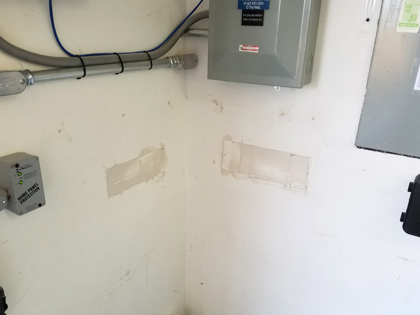
I made the access holes large enough that I could fit my drill into the wall to drill through the studs. The hole through the house siding was left smaller than the drywall to
provide a ledge for attaching the patch. After I finished drilling the holes, it only took a short time to feed the wire all the way through. Backing for the front wall patch
consisted of half the width of the stud on the left, and a piece of plywood I screwed behind the drywall on the right half. The original cutouts fit nicely back where they came
from, and a couple cycles of apply-the-drywall-mud-and-sand-when-dry left a smooth finish.
I also filled in an ugly gap about 1/2 inch wide the original contractors had left between the drywall and the bottom of the electrical panel. It's much nicer now!
A coat of paint, and I LIKE IT!
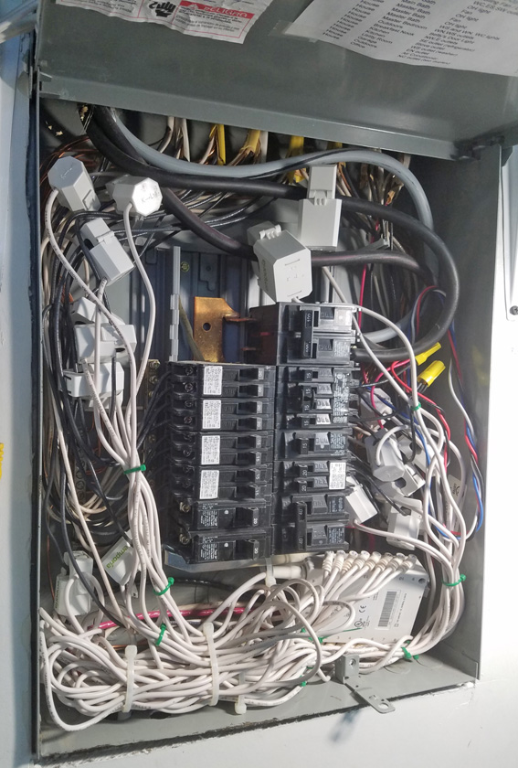
I also monitor my shop panel:
After installing the monitoring hardware in the house panel, I liked the results, and as a result, I ordered another 16 CT set from Emporia (using a discount code given me by one of their customer support people). The package arrived a couple days ago and I installed it today. This was a much simpler install, with no external conduit, cable runs, or enclosures. As it turned out, the way my panel had developed over the years, it took just the 16 CTs to monitor everything.
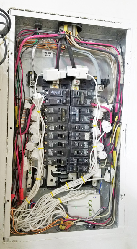
On the left is the completed installation of the CTs. There is plenty of room in the bottom of this panel to hold the main module along with
much of the extra wire.
The right shows the final installation. Some of the extra wire passes through a 1 1/4 bushing into the wall below. The WiFi antenna also exits
the metal box into the unshielded wall below.
GO BACK TO "3D Print, House, & Misc. Projects"
R. S. Mason November 2021