A Homemade Desktop CNC Machine
This is a computer model of a flexible, general purpose CNC machine.
Overview:
For many years I have wanted to have a machine which I could use to build things under computer control somewhat similar to the many machines I worked with while employed. I partially realized this dream when I got my 3D printer about a year ago. Due in large to the widespread popularity of 3D printing, the components for this type of machine have come way down in price, making it affordable to expand beyond 3D printing into such activities as CNC (computer numerical control) laser engraving and cutting, CNC routing, CNC vinyl cutting using a drag knife, and a variety of other similar activities.
The common factor in all CNC operations is that they need computer positioning in two or more axes. Many hobbyists convert their 3D printers to be able to remove the plastic extruder and mount other devices. This approach works with varying degrees or success. There is essentially no load on the movements of a 3D printer, and as a result they can be built with very lightweight components. Operations using a laser also succeed using relatively weak components. When trying to drive a router or a milling cutter however, the loads can be very heavy, and the weak structure of a 3D printer just will not hold up.
I decided to take advantage of the super-low prices available and design my own desktop CNC machine.
Design Considerations:
I had some general requirements in mind when I started this project and quickly added more. Some of the major items on my list were:
- It should be sized to fit on a small table or desktop.
- It should have a workspace of about 8 x 10 inches by several inches of height.
- It should run from a low cost computer or controller such as a Raspberry Pi or Arduino single board computer.
- It can be made using wood, MDF, or similar, but the design must support possible changing to aluminum or other metal later with a minimum of modification.
- It should be as strong as practical using low cost materials.
- It should readily accept a variety of work heads.
- It should support easy modification
- It should be self contained, but could possibly require an external computer or laptop.
The first task was to decide what the basic construction should be. Should it be a gantry machine where the entire mechanism moves back and forth over a stationary work table, with upper portions moving at right angles and up and down?
Should I make a split axis machine where the work table moves in one direction, while above it a smaller assembly moves in the other, supporting a mechanism which then moves up and down?
After sketching several possible configurations, I decided that the simplest and most rigid configuration would be a split axis machine. The next step: model it on the computer!
My Computer Model:
I fairly quickly decided on the overall dimensions and basic construction. I then started modeling it in Fusion 360, my favorite 3D CAD and CAM program. I decided that I would model all the basic structure, all the tables or carriages, and all the linear rails. I decided NOT to model simple, fairly obvious things like the motor/belt drives and axis end indicators (endstops). I did model the Z axis motor/leadscrew assembly as it had to pass through some pretty crowded real estate. Parts like the power supply and the control box were either not modeled or modeled after the actual construction.
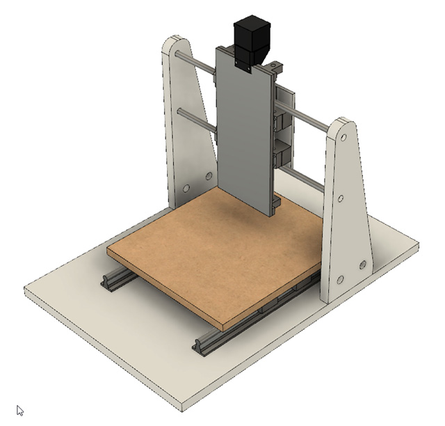
This is the final result of modeling what I now call CNC-RSM. The computer model has been maintained to show
all actual frame, table, and linear drive dimensions. The 3 axes have all been set up so they can be moved within the
model along their respective bearings with realistic travel distances. This allows virtually moving all parts throughout
their range of motion to check for clearances, travel distances, and possible interference.
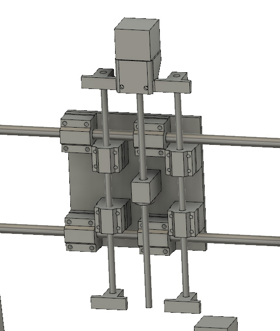
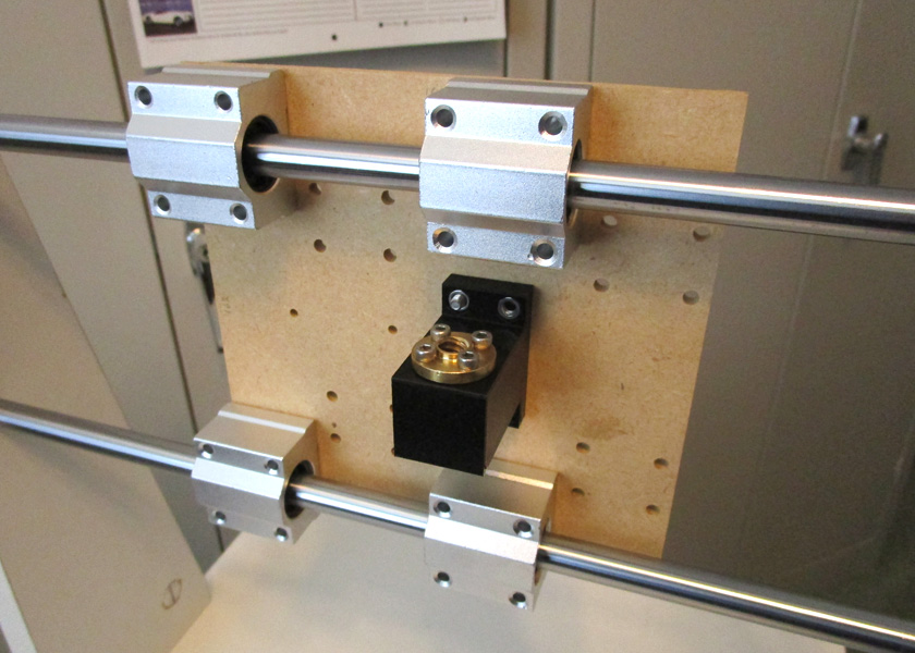
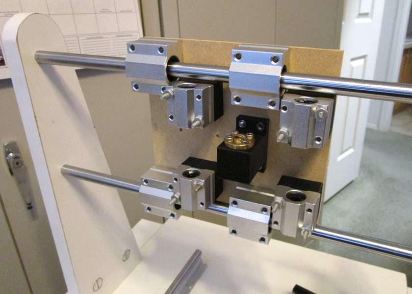
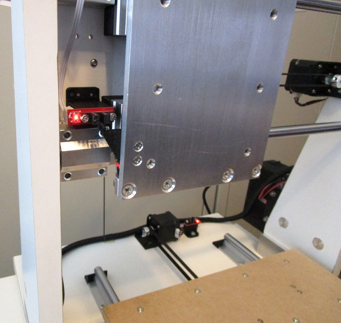
This is the XZ plate. It is probably the most complicated and congested part of the machine. It is the X axis and moves
left and right along the 12 mm linear rails driven by a lug belt. In addition to the X bushings, the plate mounts the Z bushings
which are spaced out from the plate so the 8 mm Z rods will clear the X rods. On the Z axis, the linear rods move
up and down with the Z axis mounting plate (turned off in this image for visibility) along with the driving motor and leadscrew.
The leadscrew nut is fixed in height to the XZ plate.
I was able to output a detailed drawing of the XZ plate from Fusion to make it easier to build.
Electronics:
At the same time I was doing my computer modeling, I was also evaluating control systems. Out of the many options available, there are two which seem to make the most sense:
1. An Arduino driving a Ramps 1.4 (or later) shield running Marlin software for the operating system. In Arduino terms, a shield is a custom board which plugs directly into the Arduino.
The Ramps 1.4 board is used by a large percentage of current 3D printers, and plugs directly into the Arduino (Mega version) and provides all the inputs for endstops, an LCD display, and an SD card reader along with the outputs for up to 5 stepper motors and the LCD display. The Arduino runs a copy of Marlin software, which was developed for 3D printer use as open source software. This software is VERY configurable (and very complex!), The source code not only has the provisions for many options such as automatic board leveling, but also specific code sections for many, many specific machines and can be adapted to just about whatever configuration machine you have. This combination is a popular approach for small CNC machines and results in a machine which is totally stand alone, but which can be also be connected to a computer for its control.
2. An Arduino driving a GRBL shield running GRBL software as the operating system
GRBL is another open source software package which was developed and tailored especially for CNC use. It is a much simpler and less flexible package than Marlin since basic CNC machines typically do not have the degree of complexity found in 3D printers. GRBL fans cannot see why anyone would set up a CNC machine using Marlin, but those who do say it will work just as well - and besides, they are already familiar with it after using it on their 3D printers.
I have decided to start with option 1 since I am familiar with that approach. For less than $6 in parts I can change over to GRBL and try that out also, but my original system will use the Ramps 1.4 board and Marlin software.
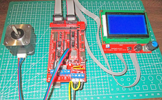
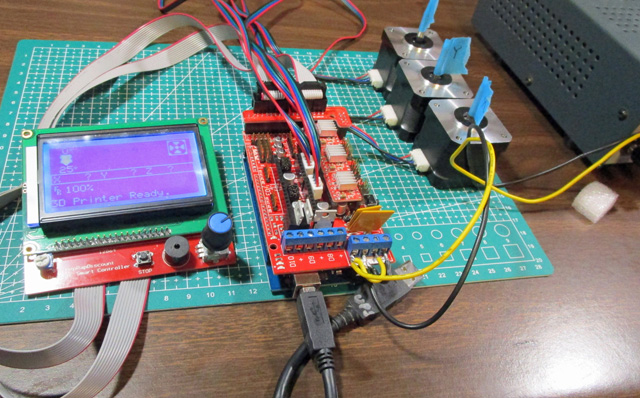
As I received the electronics, I was able to set them up on my desktop to try out. First I set up a single motor, then when I figured that out, I did all 3.
I was now ready to start making parts! Between my shop and my 3D printer I started cranking out pieces which quickly went together to create my basic machine.
Building the Machine
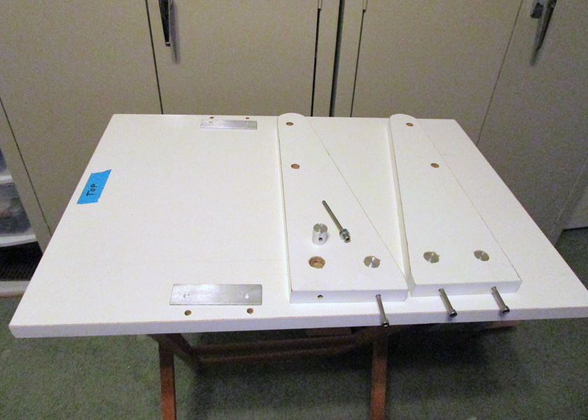
I started with a melamine clad panel, cut the base and two supports to size, then edged the cut edges with iron on strips.In machining the supports, I positioned the X
bar holes and took a light cut across the bottom in the same setup to assure accuracy. The side supports fasten to the base with through screws using a large washer plate on the
bottom of the base with the screws threading into the round nut cylinders set into the brackets. This combination seemed to give good accuracy and rigidity.
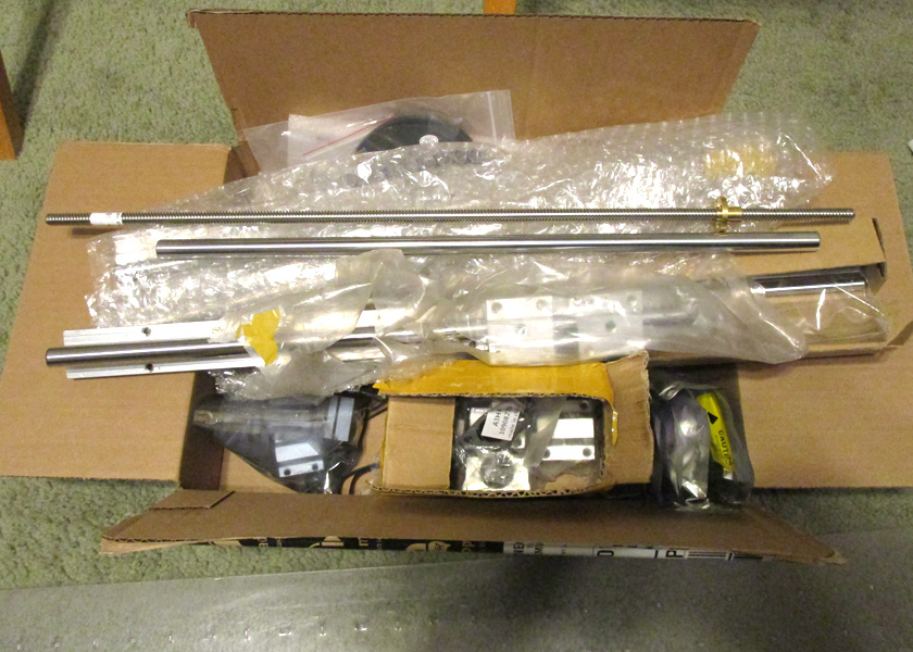
The right picture shows my box of mechanical parts from Amazon and Ebay waiting to be added.
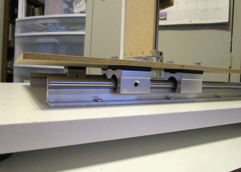
The main table which moves in the Y axis rides on 12 mm fully supported rails and open bushings.
The XZ plated which moves in the X axis is shown on the left with only the X bushings and the lead screw nut and mount. The right shows the completed plate. I decided to leave this plate
made from a tempered MDF hardboard, but I did later paint it.
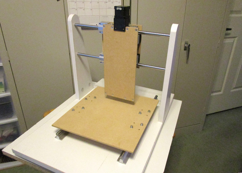
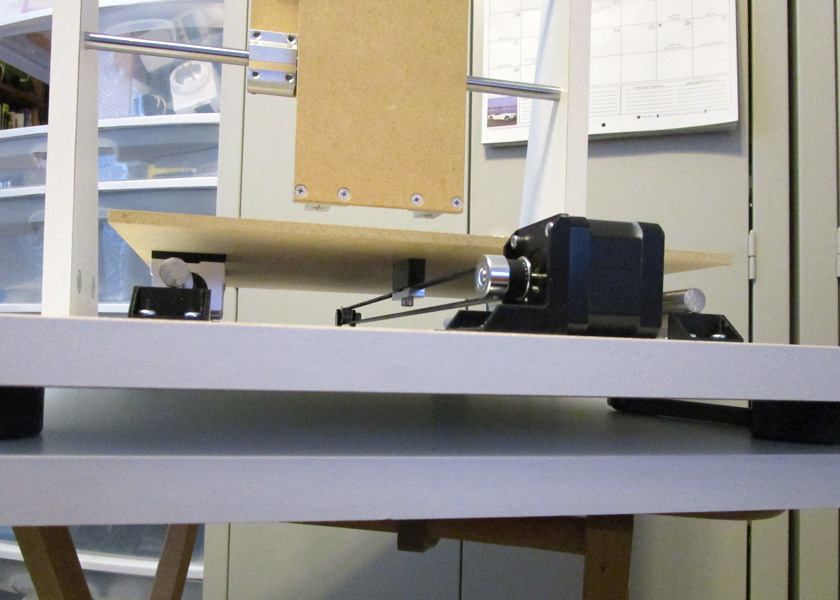
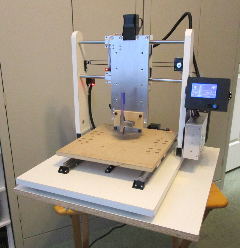
Here is the machine with all three axes assembled. The Y table which mounts the work piece and the Z table which
mounts the tool are both temporary made of 1/4 inch hard board. Both will be replaced before completion.
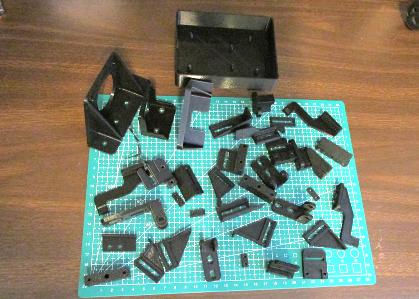
I now started designing and 3D printing many, many pieces. These included the motor mounts, pulley mounts, belt mounts,
endstop mounts, endstop flags, housings, and various spacers, nut plates, etc.
This picture is only a sampling!
Axis drives and accessories:
I decided to use belt drives for the X and Y axes, and a leadscrew drive on the Z axis. The stepper motors I started with are NEMA 17 motors, which are quite small at about 1 5/8 inches square and about 1 1/2 long plus the shaft. I used a 20 tooth pulley on each driving a lug belt which formed a loop, with one side driving the axis.
The Z axis is driven by a leadscrew directly driven by a stepper motor. This was done to prevent the Z axis and whatever tooling is attached to it from dropping when the motor power is off. I mis-judged this on the original leadscrew as once I added any weight to the Z table, it dropped slowly until reaching the end of its travel. I then changed the screw from one with an *8 mm lead (the amount it moves in one revolution) to a 2 mm lead. I don't think this shallower screw angle will back drive no matter the load!
I met my design goal axis travel of 8 X, 10 Y and several inches of Z. The final unit has approximately 8.3 inches of X travel, 10.5 of Y, and 4 1/4 of Z.
I initially used optical sensors with a black printed flag that would interrupt the sensor when the axis was at the end of its travel. These sensors were used for homing the machine and killing the power if the axis drove too far in the direction with the sensor. I put sensors only at the 0 end of X and Y, but both ends of Z.
*Note: I refer to the leadscrew's lead instead of its more common term of pitch, as there is a difference here. The pitch is the distance between adjacent threads, while the lead is the distance the thread will progress in 1 turn. Usually these are the same, but my first leadsccrew had 4 independent threads spiraling up its length (called 4 starts) which gave it a pitch of 2 mm, but a lead of 8.
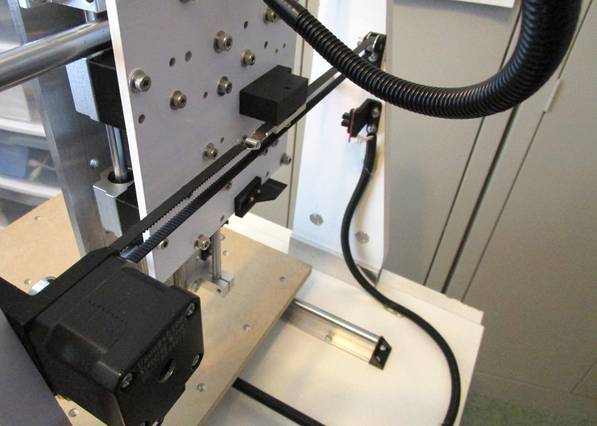
The left shows the belt drive for the X axis. You can also see the endstop and its flag. The flag enters the slot in the optical sensor as the axis reaches
its end position, blocking the light and activating the sensor.
The right shows the Y axis drive from a low viewpoint looking under the table.
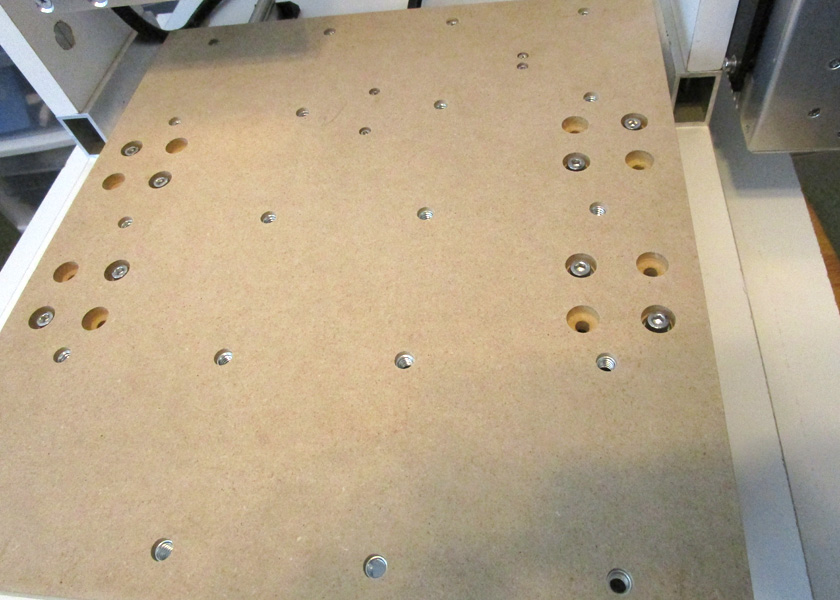
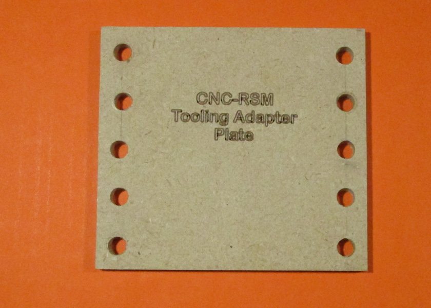
The final main work table (Y table) and the tool holding Z table have been completed as shown here. The Y table has a series of T nuts
to allow clamping the workpieces as required. The Z table also has a pattern of mounting holes to accommodate the various tools to be used.
Note from "later": This table is
not the final. I made the true final one from aluminum.
Now that all the axes have drives and endstops, it is time to wire it together with the control boards. The control consists of an Arduino computer board and a Ramps 1.4 shield that plugs into the top of the Arduino. This shield then has sockets for the stepper motor drivers and connection points for all the motors and limits, along with many features used for 3D printing that are not used here. I designed and printed a box to mount these boards along with a cover that mounts an LCD display and SD card reader. I then ran the wiring between this control box and all the electrical parts on the machine.
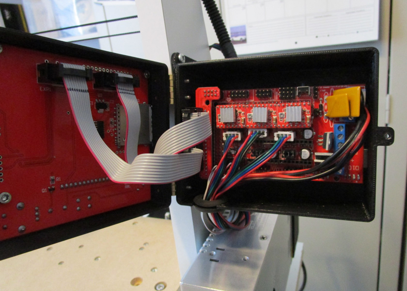
I printed a control box which mounts the Arduino and the Ramps 1.4 shield in the base and the display panel
in the lid.
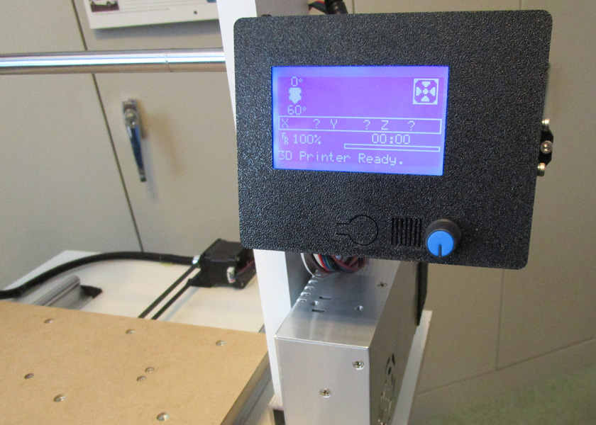
The display and front panel controls allow stand alone operation. There is an SD card slot on the left side of the cover and a USB port on the right side which allows operation while
tethered to a host computer. The front panel of the control box has a small key shaped cutout which when pressed operates the reset button inside. The small grill openings allow
sound from the beeper to be heard, and the knob is a press and turn resolver which controls all the menus and operations.
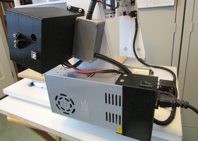
The power supply is mounted to the side support using a 3D printed adapter plate.
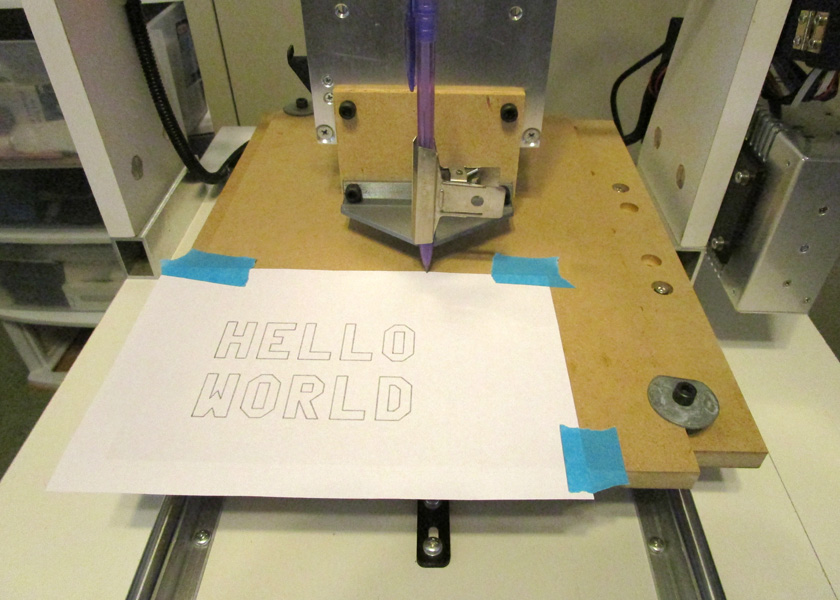
To do simple testing I printed an adapter which holds a pencil or pen with a slight spring load downward, allowing the machine to
print patterns or text. As one of my first tests, I hand coded a gcode file to print out "HELLO WORLD". It worked great!
As I learned how, I started using the proper tools to create other files of patterns and phrases.
The machine is fully operational at this point. It will home all the axes, then run a program entered as gcode. This is a format
used by automatic machines since their beginning where simple human readable lines of text move the machine point by point. There
are often hundreds of thousands of lines of gcode in a single program.
Initial
evaluation:
As I started using and testing the machine, I discovered several weakness of trying to use the complex Marlin 3D printing software to do the less complex job of running the CNC machine. The Marlin system is necessarily more complex than I need as it has to support several additional functions for 3D printing. These include controlling the feed of the extruder, verifying the filament is still present, monitoring and controlling temperatures of the extruder and the bed, and several more subtle functions. It is also set up with a massive selection of the exact equipment for it to control. For the simple CNC machine I am building, I just need control for the 3 primary axes and a small amount of control for accessories.
I then started to study the GRBL system. It appeares to be a much simpler system, and was designed to be consistent with the automated machines in industry. GRBL shields for the Arduino vary in price from about $4 to about $150. I realized that I could try the GRBL system for almost no cost at all. (I thought!)
I change to using the GRBL system after minimal testing:
I decided to give GRBL a try. I bought 2 GRBL shields for about $7 (that was the way they were offered). They accept the same stepper drivers as I already had in the Ramps 1.4 board. I figured that I could change the system over to GRBL in about an hour's time. I was almost right!
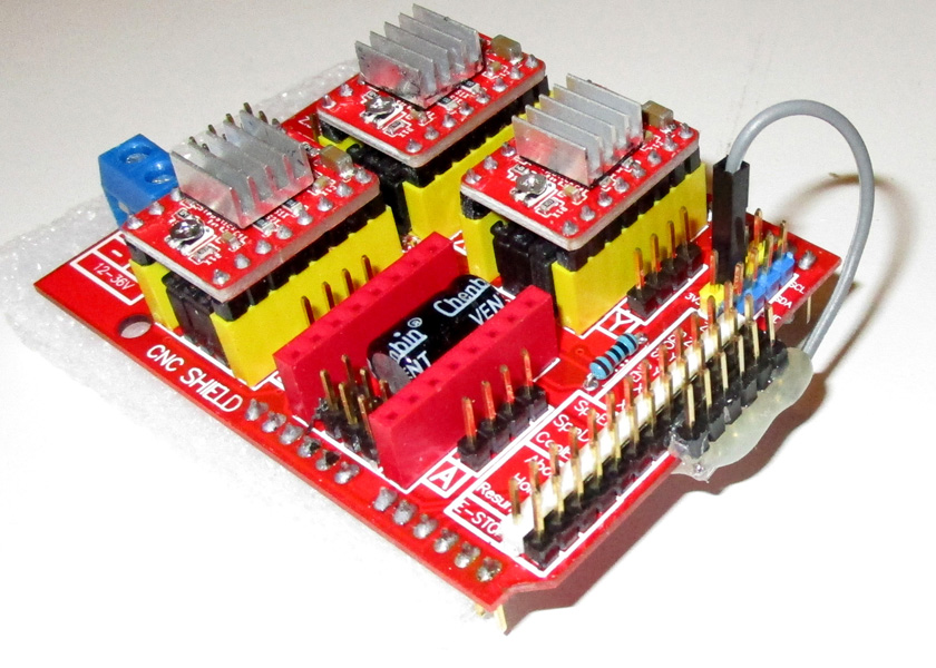
This is the GRBL shield. I plugged in the 3 driver modules from the Marlin setup and was ready to go. I did add the
short row of pins on the right to supply +5v to the endstop boards which were somewhat more elaborate than this shield
was designed to use. This shield really has almost no active circuitry on it. It is just a very convenient way to hook up
all the various wires and parts to the Arduino. You can accomplish the exact same functions if you just do a lot of
jumper connecting to the Arduino.
In a little over an hour I had the new GRBL shield in place, connected to all the motors and endstops, and loaded with the GRBL software. I powered up the machine and all 3 axes worked, and the Z axis worked over a wide range of speeds just the way is should!
However, the endstops were wonky (is that a word?). I discovered that GRBL has inputs for two endstops per axis, but it only has one circuit each with the two inputs wired in parallel. I am using 2 for the Z axis and having the two optical sensors wired in parallel does not work. I tried several wiring changes, but they did not work either. I groaned and decided that I could change the two Z endstops from optical to microswitch sensors fairly easily and did so. Now I discovered that the polarity had to be set differently between the two types of endstops, and the GRBL only has one setting that changes all of them at once. I now changed the X and Y to microswitches also. I now discovered that the way these particular microswitch endstops are wired on their small mounting boards pulls the common lead to either +5 volts or to ground. This is a good noise reducing technique, but when you have two switches in parallel, the power supply is shorted out if one switch is activated (and of course the other will not be). I made a simple wiring change on the board (I cut the normally closed lead off the switch) and now it all works fine! (Whew!)
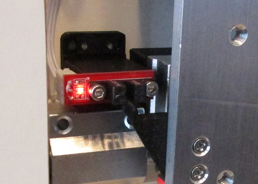
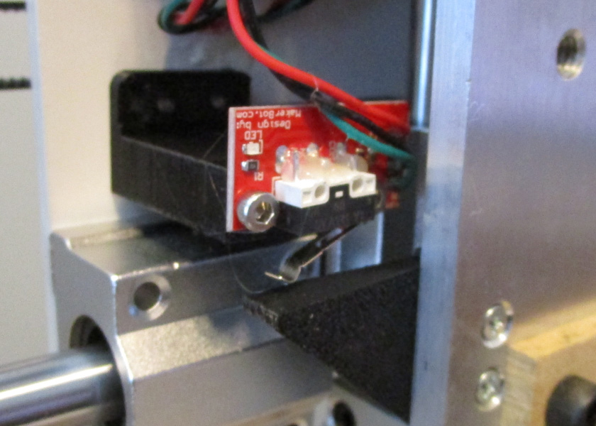
The opto-coupler endstops that I originally used are my favorites, but complications changing to GRBL forced me to replace them with the standard microswitch type.
Now after the above changes, everything is working. I found a gcode sending program (the computer operating panel for running the machine) that I like and learned to use it. In GRBL, all the machine settings that required a re-compile/upload in Marlin are available on the computer screen. There are 34 parameters, known as the $ codes, which once set, remain set through power on off cycles. These are all set by assigning a value to the $ code, for example by typing $132=110, you would set the Z axis maximum travel to 110.000 mm. Typing $$ displays a list of all 34 settings. I did a lot of adjusting of these $ codes and really like the performance I can get.
I tried running some of the text printing programs I used for the Marlin testing, and with some minor changes in the gcode they worked great. I am not happy about having to use a separate computer to control the machine, but it does allow better control and visibility of what I am doing. I also generated a couple new programs designed to run on GRBL initially, and they run just fine. In spite of the separate computer needed, I think I will stay with GRBL!
Drive changes:
Along with my change to GRBL, I decided that the small steppers I started with would be marginal when I have the machine loaded with heavy tooling and workpieces. I changed from a 12 volt motor power supply to a 24 volt one and increased the size of the stepper motors for the X and Y axes. To drive these I replaced the tiny low current stepper drivers with stand alone units with a higher current capacity. The Z axis has a very high ratio of motor to axis motion, and therefore should be fine with the original stepper and driver. I also noticed some jitter in some of the lines during my initial testing and attributed it to a dynamic belt stretching. I changed the belts on the X and Y axes from 6 mm wide to 10 mm wide belting and pulleys. This should stiffen the drive up considerably. Since I had to mount the external driver assemblies somewhere, I redesigned the control box to make it larger which also gave me room for several controls on the front panel. The larger box also eliminated the need for a separate box I had previously made just to hold excess wire lengths. My policy has been to use any supplied cables as is, unless they are too short, in which case I will extend them. Overly long cables merely have the excess coiled up somewhere.
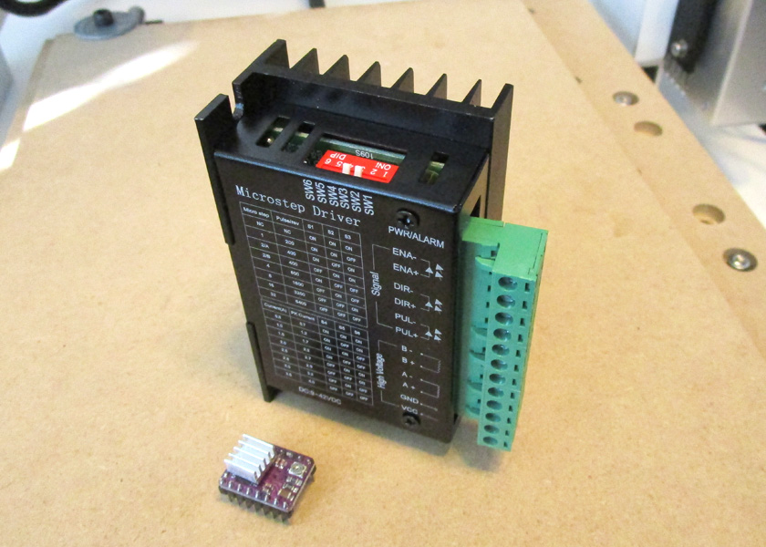
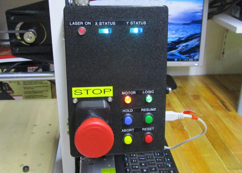
The photo on the left shows the comparison between the tiny original stepper drivers and the new stand alone units. The larger control box on the right mounts two of the
larger stepper drivers in the rear, along with the Arduino controller and the GRBL shield (including one small driver) inside. The large emergency stop switch is standard
issue for automatic machines in industry. It looks out of place, but is easy to quickly hit if something goes wrong. The large stepper drivers contain a couple of status LEDs
inside the top of the box. To be able to see these, I pressed a couple pieces of plexiglass into printed openings in the control box lid. These transmit the lights very well
to the outside.
The laser
arrives!
About this time the laser which was ordered from China arrived. I quickly printed a mount for it and installed it. I had been doing research on how to control a laser and was ready to try it. It works great! I ran a couple of brief tests as soon as the laser arrived, but knew that I would have to address the smoke and fume issues. Just about a 1 minute run really smelled up my shop and made it uncomfortable to breath. That was the end of testing until I had a ventilation system!
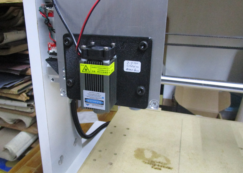
The laser is mounted and ready to go to work! This was my test image, designed to correctly label this part. It takes about 45 seconds
to complete this pattern. I ran tests on paper and on fiberboard trying many combinations of speeds and power settings. This was the
culmination of my testing (actually after the venting was done.)
Venting it:
I was not going to run the laser after my initial test run until I installed a suitable venting system. Home Depot had a dryer vent kit and was the basis for my design. This and a fan should give suitable performance. I found a Muffin fan, which is a 115 volt more powerful version of what has become know as a computer fan. I 3D printed a couple transition pieces to adapt dryer vent hose to the size of the fan. I installed the vent through the outside wall under my work bench and connected it all up. Just laying the hose behind the laser a few inches away worked wonders. I could barely smell any burning at all, and there was no noxious smoke hanging over my bench as there was before this system.
I then designed a very convoluted pickup nozzle and connected it with a length of RV sewer hose (new out of the package) to a printed transition piece to connect the 3 inch sewer hose to the 4 inch dryer vent hose and I had a working system.
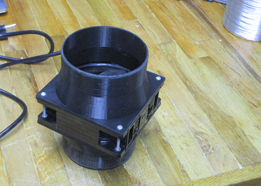
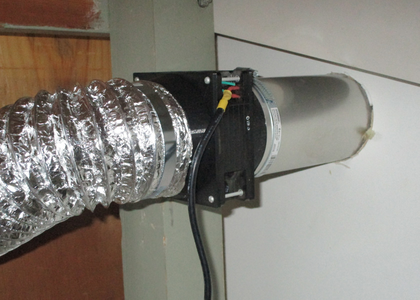
The fan is sandwiched between 2 printed transitions to connect it to the vent hose. On the right it is connected to the vent and the hose leading up to the machine. The vent comes
out on my patio with a flat plate containing 3 louvers that open when the fan is running.
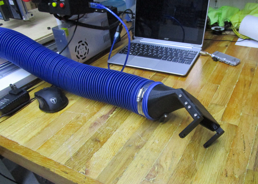
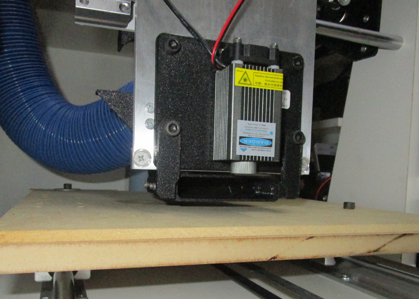
The pickup nozzle was a challenge to design, but it came out great. It attaches just behind and under the laser as shown on the right. The rear of the nozzle is held up by a wire coming
down from the top of the Z table and supports the weight of the hose.
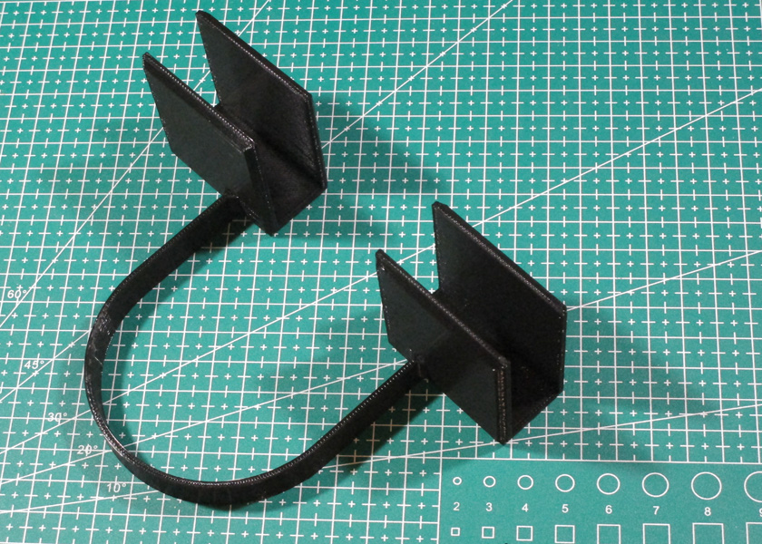
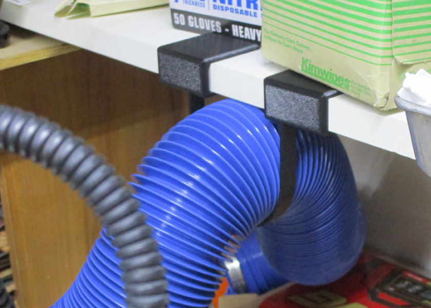
There was a problem trying to keep the hose off the rear of the build plate. It was solved by printing a hoop which slips on the front of the shelf. This holds the hose is a position where
it doesn't contact the machine, and has enough play to accommodate the full X and Z travels of the machine.
Additional
AC power control: (May 2019)
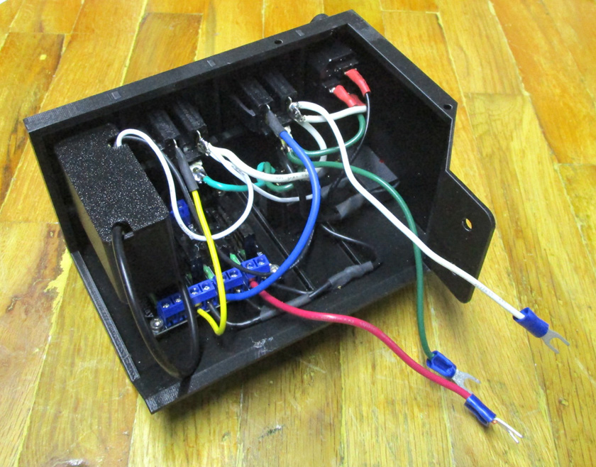
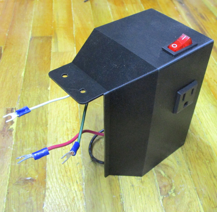
With the additional accessories to the CNC machine such as a separate computer, a laser or routing spindle, and a fan, I needed additional switches and outlets. I decided to print a small box to attach to the top of the control box and place the required switches in it. I also needed to print a larger base box for the power supply with enough space for the outlets. The power supply box would have been impossible to service using the same concept as the original one, using only the narrow end opening to wire all the internal components,so it was designed to have a 2 sided cover to attach to the 3 sided base box. The base half contains the master switch, the power input connector, and 3 AC outlets. The control top box contains 3 switches. All the switches are illuminated rocker switches.
As I started using and testing the machine, I discovered several weakness of trying to use the complex Marlin 3D printing software to do the less complex job of running the CNC machine. The Marlin system is necessarily more complex than I need as it has to support several additional functions for 3D printing. These include controlling the feed of the extruder, verifying the filament is still present, monitoring and controlling temperatures of the extruder and the bed, and several more subtle functions. It is also set up with a massive selection of the exact equipment for it to control. For the simple CNC machine I am building, I just need control for the 3 primary axes and a small amount of control for accessories.
- Even though the program is very well organized and well commented, I was never able to get the Z axis motor to run consistently the way I wanted it to. Initially I was unable to get the speeds I wanted until I discovered an additional parameter where values needed to be changed. I then thought I had it under control until I made a fairly benign change and it "blew up". It would run, stall out, then sound like a whooping siren as it rapidly changed speed repeatedly. I then had to struggle to find values where it would again run smoothly. I had none of these problems with X or Y.
- I was bothered by the fact that the operating system, Marlin supports only one coordinate system. Most machine tool systems have at least two: One is the machine coordinate system, usually with the home position at or near the limit of travel of the X and Y axes, and either all the way down or (usually) all the way up for Z. It is important for the machine to always know where it is within its own limits of movement. Software in most machines will not let it be commanded outside its usable travel. The machine coordinates are the only way to do this. The other system is the work coordinate system where the zero is usually a prominent feature on the part being made. This is always needed as the part designer never knows what machine will be used to build his part, and it is important to be able to locate the part anywhere on the machine. Sometimes there are several other systems used to define the locations of certain fixed vises or fixtures on a machine. Marlin fans claim there are work-arounds, but they seem clumsy and non-intuitive to me.
- The way Marlin is designed, any changes in the machine constants such as travel length of the axes, maximum speed, acceleration, and a number of other factors that need constant tweaking as you are setting it up, require editing the source code, re-compiling the code, then uploading it to the Arduino. This process is well automated with the Arduino special software, but it is quite time consuming with a program the size of Marlin.
I then started to study the GRBL system. It appeares to be a much simpler system, and was designed to be consistent with the automated machines in industry. GRBL shields for the Arduino vary in price from about $4 to about $150. I realized that I could try the GRBL system for almost no cost at all. (I thought!)
I change to using the GRBL system after minimal testing:
I decided to give GRBL a try. I bought 2 GRBL shields for about $7 (that was the way they were offered). They accept the same stepper drivers as I already had in the Ramps 1.4 board. I figured that I could change the system over to GRBL in about an hour's time. I was almost right!
This is the GRBL shield. I plugged in the 3 driver modules from the Marlin setup and was ready to go. I did add the
short row of pins on the right to supply +5v to the endstop boards which were somewhat more elaborate than this shield
was designed to use. This shield really has almost no active circuitry on it. It is just a very convenient way to hook up
all the various wires and parts to the Arduino. You can accomplish the exact same functions if you just do a lot of
jumper connecting to the Arduino.
In a little over an hour I had the new GRBL shield in place, connected to all the motors and endstops, and loaded with the GRBL software. I powered up the machine and all 3 axes worked, and the Z axis worked over a wide range of speeds just the way is should!
However, the endstops were wonky (is that a word?). I discovered that GRBL has inputs for two endstops per axis, but it only has one circuit each with the two inputs wired in parallel. I am using 2 for the Z axis and having the two optical sensors wired in parallel does not work. I tried several wiring changes, but they did not work either. I groaned and decided that I could change the two Z endstops from optical to microswitch sensors fairly easily and did so. Now I discovered that the polarity had to be set differently between the two types of endstops, and the GRBL only has one setting that changes all of them at once. I now changed the X and Y to microswitches also. I now discovered that the way these particular microswitch endstops are wired on their small mounting boards pulls the common lead to either +5 volts or to ground. This is a good noise reducing technique, but when you have two switches in parallel, the power supply is shorted out if one switch is activated (and of course the other will not be). I made a simple wiring change on the board (I cut the normally closed lead off the switch) and now it all works fine! (Whew!)
The opto-coupler endstops that I originally used are my favorites, but complications changing to GRBL forced me to replace them with the standard microswitch type.
Now after the above changes, everything is working. I found a gcode sending program (the computer operating panel for running the machine) that I like and learned to use it. In GRBL, all the machine settings that required a re-compile/upload in Marlin are available on the computer screen. There are 34 parameters, known as the $ codes, which once set, remain set through power on off cycles. These are all set by assigning a value to the $ code, for example by typing $132=110, you would set the Z axis maximum travel to 110.000 mm. Typing $$ displays a list of all 34 settings. I did a lot of adjusting of these $ codes and really like the performance I can get.
I tried running some of the text printing programs I used for the Marlin testing, and with some minor changes in the gcode they worked great. I am not happy about having to use a separate computer to control the machine, but it does allow better control and visibility of what I am doing. I also generated a couple new programs designed to run on GRBL initially, and they run just fine. In spite of the separate computer needed, I think I will stay with GRBL!
Drive changes:
Along with my change to GRBL, I decided that the small steppers I started with would be marginal when I have the machine loaded with heavy tooling and workpieces. I changed from a 12 volt motor power supply to a 24 volt one and increased the size of the stepper motors for the X and Y axes. To drive these I replaced the tiny low current stepper drivers with stand alone units with a higher current capacity. The Z axis has a very high ratio of motor to axis motion, and therefore should be fine with the original stepper and driver. I also noticed some jitter in some of the lines during my initial testing and attributed it to a dynamic belt stretching. I changed the belts on the X and Y axes from 6 mm wide to 10 mm wide belting and pulleys. This should stiffen the drive up considerably. Since I had to mount the external driver assemblies somewhere, I redesigned the control box to make it larger which also gave me room for several controls on the front panel. The larger box also eliminated the need for a separate box I had previously made just to hold excess wire lengths. My policy has been to use any supplied cables as is, unless they are too short, in which case I will extend them. Overly long cables merely have the excess coiled up somewhere.
The photo on the left shows the comparison between the tiny original stepper drivers and the new stand alone units. The larger control box on the right mounts two of the
larger stepper drivers in the rear, along with the Arduino controller and the GRBL shield (including one small driver) inside. The large emergency stop switch is standard
issue for automatic machines in industry. It looks out of place, but is easy to quickly hit if something goes wrong. The large stepper drivers contain a couple of status LEDs
inside the top of the box. To be able to see these, I pressed a couple pieces of plexiglass into printed openings in the control box lid. These transmit the lights very well
to the outside.
About this time the laser which was ordered from China arrived. I quickly printed a mount for it and installed it. I had been doing research on how to control a laser and was ready to try it. It works great! I ran a couple of brief tests as soon as the laser arrived, but knew that I would have to address the smoke and fume issues. Just about a 1 minute run really smelled up my shop and made it uncomfortable to breath. That was the end of testing until I had a ventilation system!
The laser is mounted and ready to go to work! This was my test image, designed to correctly label this part. It takes about 45 seconds
to complete this pattern. I ran tests on paper and on fiberboard trying many combinations of speeds and power settings. This was the
culmination of my testing (actually after the venting was done.)
Venting it:
I was not going to run the laser after my initial test run until I installed a suitable venting system. Home Depot had a dryer vent kit and was the basis for my design. This and a fan should give suitable performance. I found a Muffin fan, which is a 115 volt more powerful version of what has become know as a computer fan. I 3D printed a couple transition pieces to adapt dryer vent hose to the size of the fan. I installed the vent through the outside wall under my work bench and connected it all up. Just laying the hose behind the laser a few inches away worked wonders. I could barely smell any burning at all, and there was no noxious smoke hanging over my bench as there was before this system.
I then designed a very convoluted pickup nozzle and connected it with a length of RV sewer hose (new out of the package) to a printed transition piece to connect the 3 inch sewer hose to the 4 inch dryer vent hose and I had a working system.
The fan is sandwiched between 2 printed transitions to connect it to the vent hose. On the right it is connected to the vent and the hose leading up to the machine. The vent comes
out on my patio with a flat plate containing 3 louvers that open when the fan is running.
The pickup nozzle was a challenge to design, but it came out great. It attaches just behind and under the laser as shown on the right. The rear of the nozzle is held up by a wire coming
down from the top of the Z table and supports the weight of the hose.
There was a problem trying to keep the hose off the rear of the build plate. It was solved by printing a hoop which slips on the front of the shelf. This holds the hose is a position where
it doesn't contact the machine, and has enough play to accommodate the full X and Z travels of the machine.
With the additional accessories to the CNC machine such as a separate computer, a laser or routing spindle, and a fan, I needed additional switches and outlets. I decided to print a small box to attach to the top of the control box and place the required switches in it. I also needed to print a larger base box for the power supply with enough space for the outlets. The power supply box would have been impossible to service using the same concept as the original one, using only the narrow end opening to wire all the internal components,so it was designed to have a 2 sided cover to attach to the 3 sided base box. The base half contains the master switch, the power input connector, and 3 AC outlets. The control top box contains 3 switches. All the switches are illuminated rocker switches.
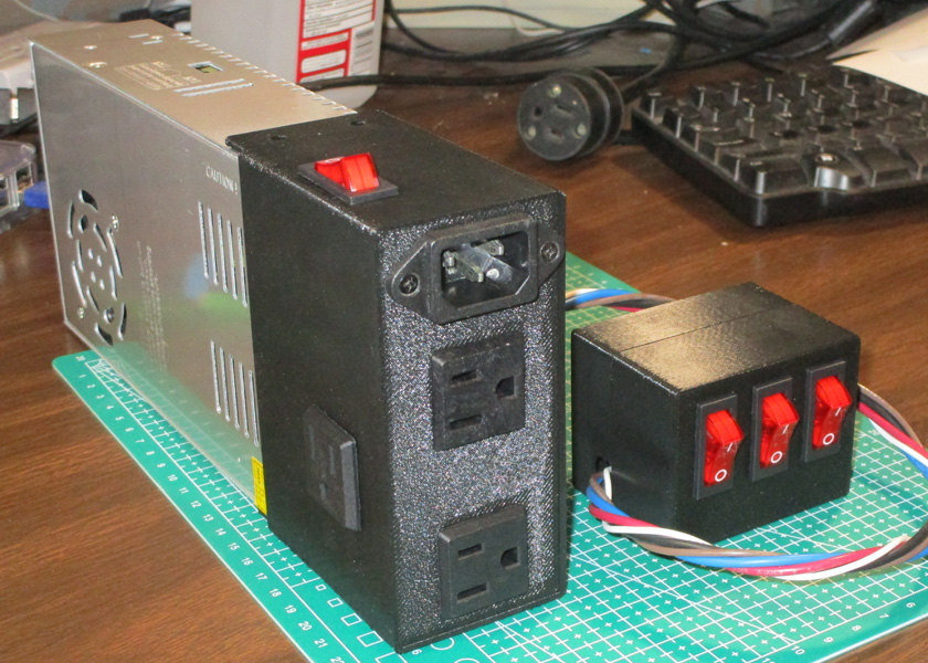
The power supply bottom box is connected to the switch box with a 5 wire harness
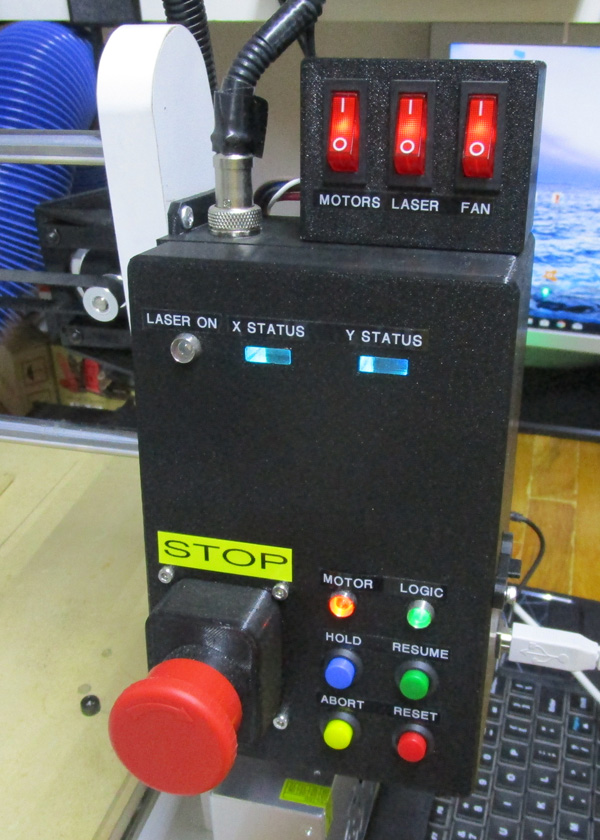
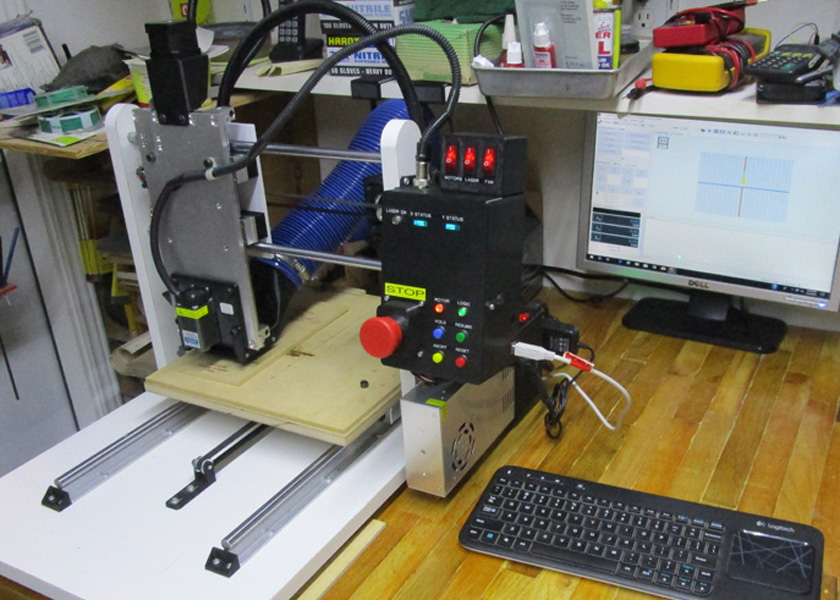
The added switches certainly make it more convenient to operate the system. The MOTORS switch controls power to the 24 volt power supply, the LASER and FAN control their
respective outlets, and the computer can plug into a dedicated, always-on outlet. The master switch on the power supply controls everything but the computer.
On the right is the almost final configuration of the CNC machine.The "almost" is because I have a piece of aluminum jig plate on order to use for the table.
The MDF table just is not flat enough for precision work.
I have noticed a recurring problem with my new switches and power control. Often when I switch one of the switches, MOTORS, LASER, or FAN, the system goes into alarm mode. This shuts me down until I do an alarm reset and usually requires me to re-home the machine. Obviously, the switching transients cause enough disturbance of some logic circuits to do that. It is usually in the form of an "out of bounds" alarm resulting from an erroneous limit switch trigger. I can avoid the problem by turning off the hard limits function. I am not willing to do this long term, as it leaves me vulnerable to crashing the machine in the case of an error in my gcode, or if I neglect to reset the zero in some special cases.
To solve the problem, in initially considered putting a number of ferrite cores around various wires to try and suppress the surges. This is pretty much a hit and miss proposition, although my targets are narrowed considerably by the fact that it is the hard limits causing a problem. Instead of trying to supress the surges, I decided to eliminate them in the first place. I figured that if I use solid state relays (SSRs) which use zero crossing technology, switching only as the AC power passes through the zero voltage point, there should be no transients generated.
Doing an online search, I found a series of boards available at a very reasonable price which contain 2, 4, or 8 small solid state relays. These do truly switch only at zero crossing and are capable of switching up to 2 amps AC each with only a logic level input. I purchased a 4 relay board and totally rewired both the small switch box on top of my control unit and the extension on the rear of the power supply where I added the outlets for the laser and the fan, and controlled input power to the power supply itself.
To implement this change, I needed to rewire the switches to control only very low current 5 volt signals. These activate the solid state relays located near the outlets and power supply which in turn switch the same items the switches used to switch directly at 115 volt full current. I also decided to provide a totally separate 5 volt power supply to drive only these switches and relays. This gives me true isolation which I would not have if I used the existing 5 volt logic supply. There were a couple of nitpic items to handle such as the switch lighting. Originally the switches were selected because the toggle lights up when the switch is on. This is very handy to quickly check their status. The lights were tiny neon bulbs which work only above 65 volts. In the new configuration, I did not wire to these lights but installed a small LED above each switch which truly do light at 5 volts.
The largest problem this change caused was that the new SSR board and the 5 volt power supply would not fit in the existing housing, or even one where I just lengthened it some reasonable amount. I ended up leaving the length the same, but increasing the height and width by about an inch each. As it still had to attach to the existing power supply, one end is the original size then it tapers out and up at 45 degrees to the larger dimension. This gave enough room for the added SSR board and the 5 volt power supply in its own 3d printed case holding the board from a cell phone charger.
These changes seem to have totally solved the problem!
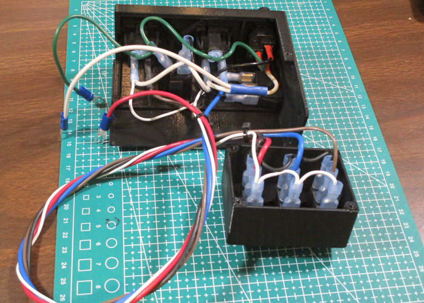
This is the enlarged case (without its cover) showing the 5 volt power supply at the far left with the 4 circuit SSR under it. The 3 wires hanging out
attach to the 24 volt power supply which is switched by one of the relays. The right view is of this box as it will be seen after attaching it to the 24v power supply.
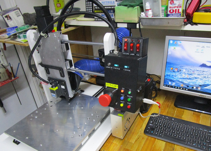
Here is the (semi-) finished machine. It shows the new aluminum table, the laser and vent, and the latest switch changes.
GO BACK TO "Machine Shop Projects"
R. S. Mason May 2019