A 3D Printed Scale Model Ford Flathead Engine
Overview:
Even before I bought my 3D printer, I had marveled at a series of printed automotive engines a fellow on-line had designed and built. His screen name is ericthepoolboy, but his real name is Eric Harrell. He has designed and made available at no cost through Thingiverse, all the design files for about 6 different engines and several transmissions. He has also designed a Toyota driveshaft and rear axle assembly. Now that I am about 1 1/2 years into using my 3D printer, and after seeing the results of a friend building one of Eric's engines, I decided I would tackle building one. The flathead Ford engine was my immediate choice since I had worked on so many of these (full size) engines in my early car-owning and hot-rodding days.
This is a significant departure from the majority of the printing I have been doing. Mostly I have been designing and printing specific parts for my own projects and have only printed a few small items from others' designs. This engine is the largest project I have yet attempted, and it is all from Eric's designs.
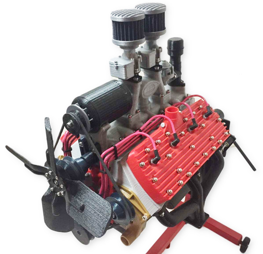
This is the published photo from Thingiverse, the location where Eric makes his designs available to others. It was the inspiration for starting the project myself.
Eric's models are beautifully designed at 35% life size. He has gone overboard to exactly duplicate the actual engines. Most of the major parts are attached using magnets
which position and hold the parts very well, but allow an easy disassembly and re-assembly. There are about 120 magnets used in the construction of this engine. A full
hardware kit is offered by Maker Rx (makerrx.com) for just under $100. It is worth every penny! All the screws, nuts, bearings, threaded rod, motor, speed controller, valve springs, etc. are
included- everything you need other than the printed parts. It would take easily that much in your time alone to track down all the specific parts needed!
I was also planning to build an engine stand of his design, but the hardware kit has been sold out since before I started this project. I have built a quick working stand,
and am now designing my own scale model of a mechanic's engine stand.
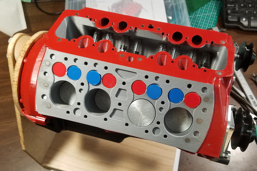
For my model I chose a red block with some cast iron color showing. I did this by printing the block in a gray color, then carefully masking and painting the majority of the surface with a paint color called Cherry Red.
I then printed the heads and intake manifolds (upper and lower), along with all the other small parts scheduled to be a bright, shiny silver. I chose a red filament for the timing gear cover and the water pump bodies. After printing them and installing them on the painted red block, I realized that the two reds clashed badly, and I re-printed those parts in silver. I originally printed the exhaust headers black, but decided they needed more bling, so I reprinted them, also in silver.
Here are a few of the more relevant Specifications of this build:
- I initially printed 257 parts, including some trial parts, a couple reprints, and several intentional overages. 210 parts were actually needed.
- The total printer run time was 251 hours, 44 minutes to
print these parts - about 10 1/2 days!
- It used 1819.4 grams of filament - about 4 pounds
(numbers from my slicer)
- The largest print, the engine block, took 66 hours and 22 minutes to print - almost 3 days!
- The
gcode file for the engine block contained over 8.7 million lines of
code! That's about 145,000 pages at 60 lines per page, or 145
reams of paper double sided, but I didn't print it out.
- It took me just over 3 weeks from start to completion. That time did include a 3 day motorhome rally, so really just under 3 weeks!
A note about magnets: There are about 120 magnets used in this model to hold parts together, yet allow them to be easily removed. These magnets are incredibly small at 4mm diameter and 2mm thick. That is well under 3/16 inch in diameter and half that thickness. Everywhere two magnets are used to hold things together, one must have its north pole meeting the other's south pole. As the magnets are not marked I had to come up with a technique of easily and reliably installing every magnet correctly. I initially made a simple rig sandwiching a magnet between a small piece of wood and a layer of cardboard taped together. I marked it that if a magnet was attracted, the magnet was correct for the block, if it repelled, it was right for an accessory. This was cumbersome, and it was so easy and common for a magnet to slip once it was removed from the stack of magnets, forcing you to start over.
I then discovered that I had a magnetic catch designed for a necklace. Its magnets were slightly larger than the 4mm magnets I was using, and obviously the two halves had opposite polarities. I labeled one half "block" and the other "acc" and I was in business. To use this tool, I would use the appropriate half for the place I was installing magnets. I would lay out several magnets on my table a couple inches apart, so they wouldn't fly together, and started applying my adhesive. To handle the magnet I would move the tool over a magnet which would jump up and attach itself with the correct polarity. I would then apply more glue to the magnet and put it in place, using the tool as a handle. I would then slide the tool off sideways and wipe any excess glue from the surface around the magnet. This process went smoothly and quickly, and I never got a magnet installed upside-down.
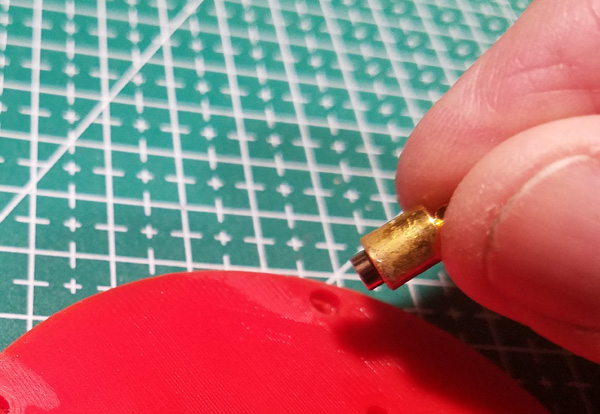
Here is an example of installing the very tiny magnet.
Printing:
I started by going through the print list in the manual and assigning the color I wanted for each piece. I then started printing all the silver color parts (as defined at that time) There were quite a few. I was really pleased with the results of printing with this filament. I bought it from Amazon, choosing it by the pictures and descriptions. Descriptions are often blatantly over rated, and pictures can be deceiving, but I took the chance. I could not be happier with the results! The parts look like they are really made of polished aluminum! The filament I bought was Mchyi Silk Silver PLA. A friend bought the same brand in Silk Red, and the results looked like red anodized aluminum, almost a candy apple red.
After printing a couple small samples to check out the filament, I printed one of the cylinder heads! I was thrilled with the outcome!
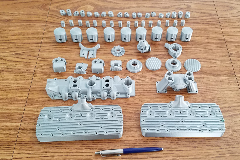
I then proceeded to print the balance of the silver parts (as initially defined). The top row contains all the cam lobes and bearing blocks.
The second row has the valve lifters, the third the pistons, then the generator bracket and fan, the fuel pump, and the distributer. Next
come the carburetors and air filter top and bottoms, then the intake manifolds -lower and upper, followed by the heads. The pen
is included to give scale to the items.
Next I decided since I had to print the block sometime; it might as well be now.
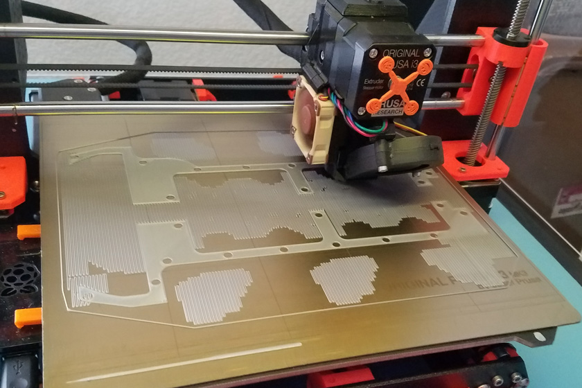
The first picture shows the block 42 minutes in at the completion of the first layer. You can see just how close to the maximum capacity of my printer it came.
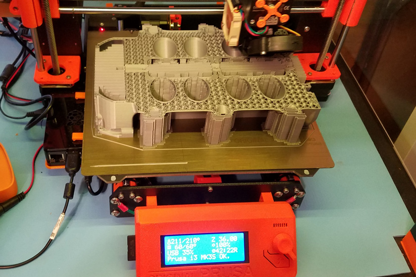
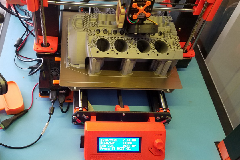
The second picture shows the progress after 24 hours, the third, after 48 hours.
In the last 2 pictures, you can clearly see the infill pattern, which is only 15% dense, while it is solid at all the surfaces.
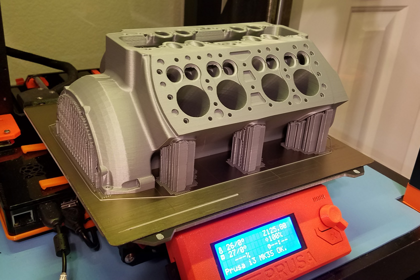
Finally, after over 66 hours, the block was complete! I was, and am, totally happy and amazed with the results! (and VERY relieved that there were no "glitches"!
I then proceeded to print all the
remaining parts, one color at a time. I usually printed a number
of different parts at a time, up to 20, to reduce the total number of
printing cycles, although that did not really reduce the total printing
time. In all, I printed 36 loads of parts, not counting the parts
I printed over to change color.
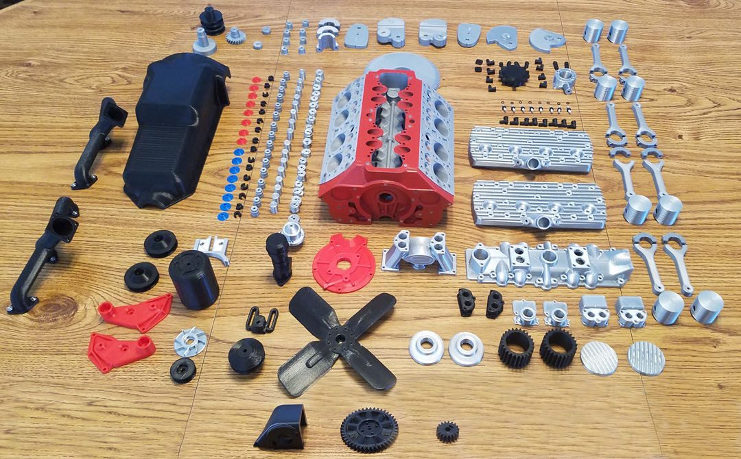
After I finished printing all the required parts, in several different colors of filament, I staged the parts and took this "group" shot. Altogether I printed in silver, gray, black,
red, and blue. Even thought I generally was going for realism in my color choices, I went with Eric on the valve colors. Making them blue and red makes it so much
easier to recognize which are the exhaust and the intake valves when demonstrating. The red timing cover and water pump bodies and the black exhaust headers were
later reprinted in silver. The final total print count was 210.
After tearing down the setup, I discovered that 3 parts had been missing from the shot. I located the parts and photographed them separately on the same table. Using
Photoshop Elements, I added the 3 parts to the bottom, did some touch up and got the above picture of all the parts.
Assembly:
OK, I have all the parts needed, now the delicate and and sometimes repetitive part starts. I need to put them together! Fortunately, Eric did a great job writing a detailed manual with a number of good hints about specific parts!
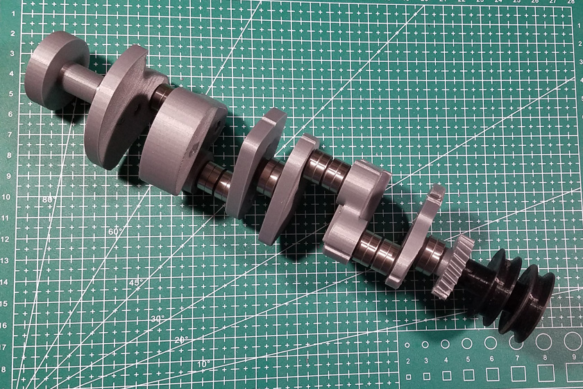
The first item I assembled was the camshaft. I had printed 20 separate parts consisting of 16 cam lobes 3 bearing mounts, and one spacer. These were assembled by stacking them over a 3 mm threaded rod and a 2 mm smooth rod running through alignment holes in each part. Adding the cam gear completed the assembly. I first assembled the 20 pieces dry, clamped them between nuts on the threaded rod and took some measurements. The manual specifies what the assembled dimensions should be for the front half, the rear half, and the total length. All of my dimensions were significantly over. I calculated that each element was, on average, about 0.12 to 0.15mm (.005 to .006 inches) oversize.
I started trying to sand down individual parts without much success. I then had a flash of inspiration: why should I try reworking them when I can re-print them with very little effort. I calculated the percentage of their current size I needed to hit the dimensions (if I recall, it was 98.7%), set the Z scaling for that scale factor and re-printed them. I re-stacked them, and the dimensions were right on! Next I took them apart and re-assembled them one piece at a time, gluing each piece to the previous part, and adding ball bearings as required. When I finished and added the cam gear, I had an amazingly realistic camshaft!
OK, I have all the parts needed, now the delicate and and sometimes repetitive part starts. I need to put them together! Fortunately, Eric did a great job writing a detailed manual with a number of good hints about specific parts!
The first item I assembled was the camshaft. I had printed 20 separate parts consisting of 16 cam lobes 3 bearing mounts, and one spacer. These were assembled by stacking them over a 3 mm threaded rod and a 2 mm smooth rod running through alignment holes in each part. Adding the cam gear completed the assembly. I first assembled the 20 pieces dry, clamped them between nuts on the threaded rod and took some measurements. The manual specifies what the assembled dimensions should be for the front half, the rear half, and the total length. All of my dimensions were significantly over. I calculated that each element was, on average, about 0.12 to 0.15mm (.005 to .006 inches) oversize.
I started trying to sand down individual parts without much success. I then had a flash of inspiration: why should I try reworking them when I can re-print them with very little effort. I calculated the percentage of their current size I needed to hit the dimensions (if I recall, it was 98.7%), set the Z scaling for that scale factor and re-printed them. I re-stacked them, and the dimensions were right on! Next I took them apart and re-assembled them one piece at a time, gluing each piece to the previous part, and adding ball bearings as required. When I finished and added the cam gear, I had an amazingly realistic camshaft!

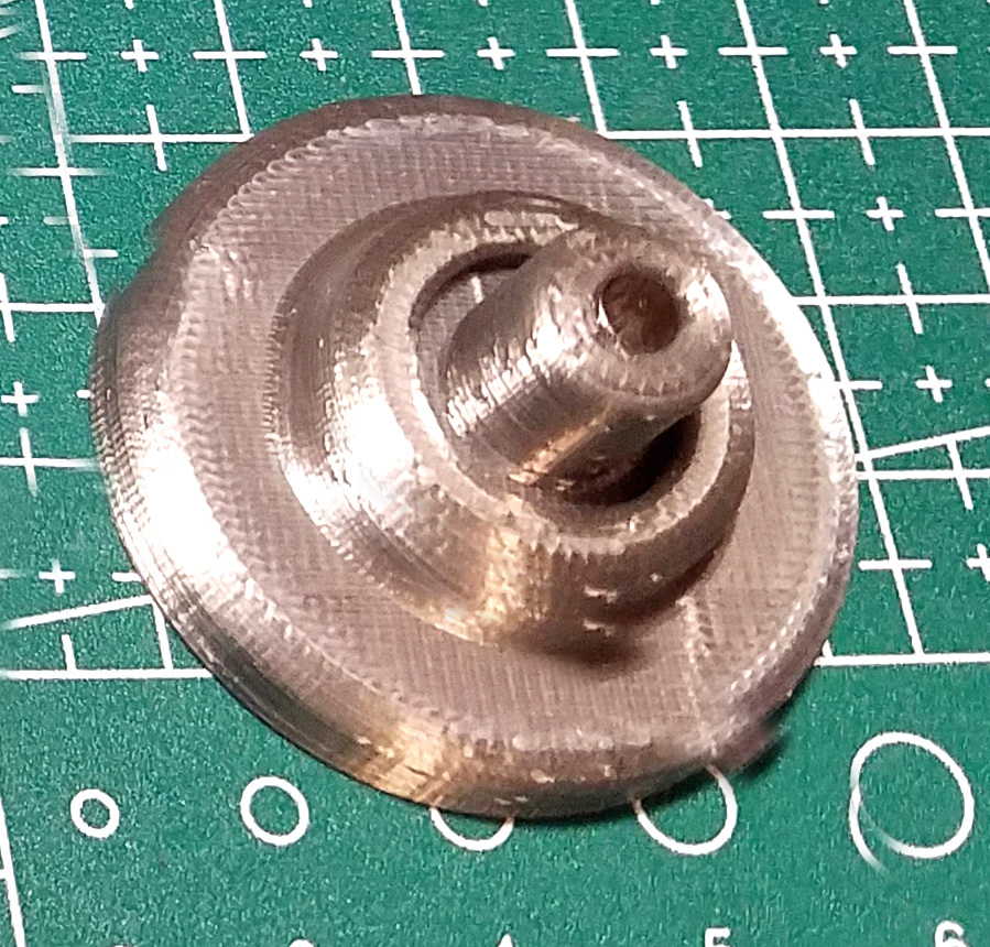
These are the parts I had to work with. Note the larger hole in the center for the threaded rod, and the smaller, off-center hole for alignment.
Each cam lobe has an identifying number printed into one side to prevent mis-positioning it.
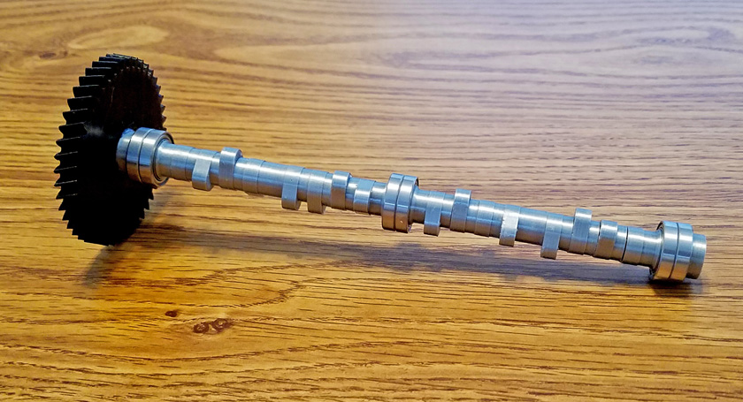
And here is the completed camshaft. Is it a model, or is it the real thing?
The completed camshaft slid easily into the bearing holes in the block. Since it was now the correct length, the lobes lined up nicely with all 16 lifter holes in the block. After carefully positioning it for best alignment, 3 setscrews on the bearings locked it securely in place.
I decided to do something easy next, and chose the cylinder heads. The only assembly on the surface of the heads was purely decorative. There are 24 head studs on each head (which means this is a 1939 to 1953 engine as the earlier ones had 21 studs). These heads are held down with acorn nuts on the studs, so for each stud hole, I drove an 8mm long set screw into the hole leaving about 2mm showing. I then screwed an acorn nut on this screw and tightened it against the head. I then used a similar method to install the spark plugs, and there were a couple of plugs near the water outlet to be installed. The holes for these were oversize and too shallow, so I drilled a hole in the bottom surface and threaded the screws into those. The heads also each needed to have 6 magnets glued in recesses on the bottom of the head. The heads were now finished.
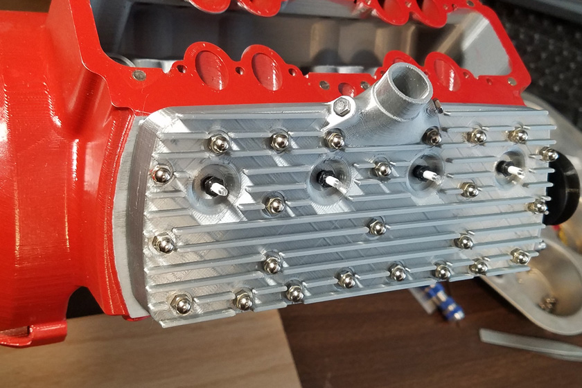
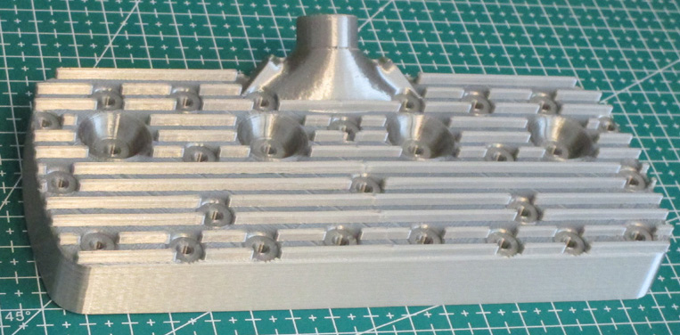
This is what the finished head looks like, with its chrome acorn head nuts, its spark plugs, the 2 water plugs, and the unseen magnets holding it to the block.
I am particularly pleased with the spark plugs which I printed by changing the filament twice. I was blown away by the realism of the resulting plugs!
I next assembled the intake manifold. It consists of a lower and an upper manifold, two 3 piece carburetors, a filler pipe and a fuel pump. These parts were all attached with 3mm and a few 2mm screws. The manual did not specify, so I assumed that the air cleaners should be glued to the top of the carbs, but I did not want to do that. If you just placed them on top they could easily be knocked off, so I re-designed the air filter bottom to slide into the carb throat and attach with a magnet.
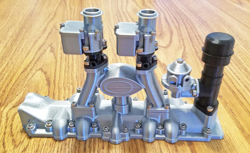
The completed intake manifold assembly is quite elaborate. The two manifold sections, the 3 sections of each carburetor, and the filler pipe and
fuel pump are all attached with screws. There are also 8 magnets glued to recesses in the bottom for attachment to the block. The screws and nuts
which appear to attach it, are all for appearance only.
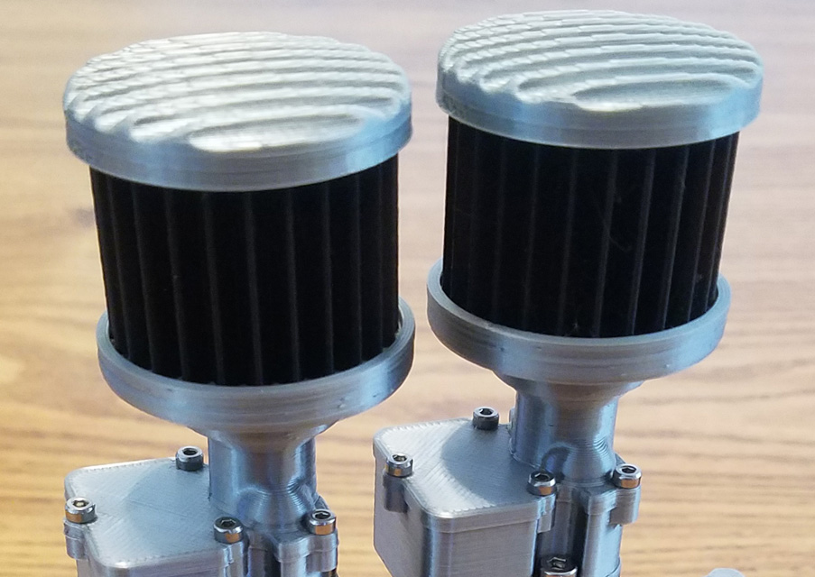
To avoid having to glue the air cleaners in place, I re-designed the bottom piece to include a stub that fits the carburetor throat, and embedded a magnet
in the end. In addition, I surface glued a magnet to the flat at the bottom of the carb throat to hold it in place. The installed completed filters are shown
on the right and look identical to the stock ones - except that these are removable and secure!
The next major assembly I tackled was the crankshaft. This was built up of a number of individually printed parts similar to the way the camshaft was, except that this could have no central core. The offsets to be driven by the connecting rods prevented this. As a result the alignment problem was infinitely more difficult. When I first assembled the crankshaft without glue, the flywheel and the crank pulley were both way out of true, with unacceptable wobble. Also, the center main bearing was at least 1/8 inch out of alignment with the two end ones. There are grooves in each part to aid in alignment, and I had originally just "eyeballed" them.
I did two things to help with the alignment. First, I made a flat faced tool for my drill press which I used to lightly sand the top printed surface of each part. The tool served as a backing to the sandpaper and assured that it was parallel with the bottom surface (I had checked the tool with a dial indicator.) I only took two strokes of the paper which was enough to remove any small blips of filament on the surface that might cause the next part to be clamped at a small angle.
Secondly I got a straight rod from my shop that was the correct size to fit the alignment notches in the parts. This turned out to be far more accurate than my first method. After assembling it again, the flywheel ran with less than 1/32 inch wobble, certainly close enough!. The pulley still had too much wobble, and the center main bearing still was somewhat off. To get the center main aligned, I just looked at which joint could be pivoted to move it in the right direction and through a series of very minor adjustments at several crankshaft throws, I managed to get the center main almost perfect. Now the flywheel and the center main were fine. I corrected the pulley wobble by using several layers of paper under one edge and shimmed it true. Mission accomplished!
This is the completed and aligned crankshaft, less the flywheel. Every moving surface on the crank uses a pair of ball bearings. Each
connecting rod and all 3 main bearings each have two.
Now we are building an
engine! The crankshaft laid nicely in the bottom of the block and
was secured by the 3 main bearing caps. The pistons and
connecting rods were then assembled. Next the pistons were
installed into the engine just as in a real engine, except there is no
need to compress the rings. Each connecting rod clamps securely
to a pair of ball bearings on the crankshaft using its rod bearing cap
and screws threaded into brass inserts. Rotating the crank now
gives the satisfying sound of the pistons sliding in the cylinders and
you can see them operating in sequence.
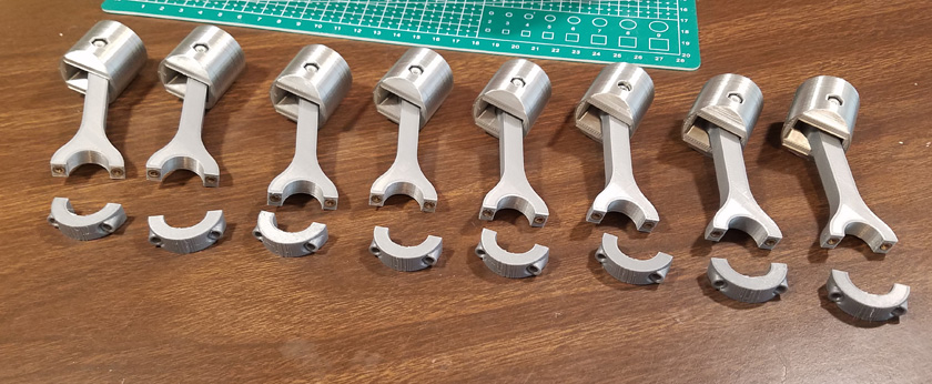
The pistons and rods are assembled and ready to be installed into the engine.

The crankshaft is installed and all the pistons and rods are in place.
The valves were probably the most tedious portion of this build. Each valve is first assembled with a valve guide on a cut-down socket head cap screw. The screw makes its own threads into the valve. Next a lifter with a hex head screw threaded into its top is inserted into the block, the valve and guide are dropped in place and the clearance is checked (with the cam 180 degrees from the lobe). By trial and error, the lifter is adjusted until there is essentially no clearance, but no pressure on the lifter. Now the valve has the spring added, held in place by a retainer. This assembly is placed into the block and the guide is worked into location (I used a small pointed bamboo stick between the raised valve and its seat) and locked in place with a setscrew. The setscrews are threaded into holes in the block. The intake ones are just slightly deeper than the setscrew, but the exhaust are very deep and require about a hundred turns to insert them into position. Thank you Mr. electric screwdriver! Once that valve is secured in place you are ready to tackle the next one. I felt a real sense of satisfaction when I finished installing the final valve!
We now have a pretty much completed engine! (short block) Turning the crankshaft causes the pistons to go up and down and the
valves to open and close in the correct timing sequence for the 4 cycle engine to theoretically run.
My temporary engine stand can be seen in this picture. It made most of the operations on the engine so much easier than if I did not have it.
The remaining parts of the build
were
fairly routine. The engine pan required 8 magnets to be glued in
place along with a number of setscrews and nuts to simulate it being
bolted in
place
The two water pumps, the fan and the generator all had pulleys mounted on a pair of ball bearings. I made several simple modifications to stiffen and remove play from these, but they all went together without problem. Once they were in place, a pair of black rubber bands became the v-belts to drive all the accessories. The distributer is bolted to the timing cover, and the distributor cap is attached to it with 4 magnets in each part.
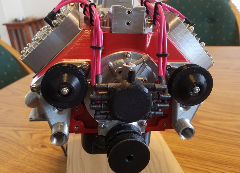
This shows the water pumps, the distributor, and its cap. Each of the cap's wire ports has a magnet glued into its end.
The wiring harnesses were by far the most challenging pieces remaining. The hardware kit came with 7 feet of 12 ga. solid commercial home wire. It is very stiff and has identifying printing on it that would be very distracting. I hoped it could be removed, but feared it might be printed under the tough clear outer coating. I tried some rubbing alcohol with no results, then I tried some some acetone. One quick wipe and the printing totally disappeared! What a relief!
Each harness consists of 4 lengths of wire running from the distributor cap to a spark plug. Each end has a printed boot with the distributor end containing a magnet to attach to a mating magnet in the distributor cap. The spark plug end has a hollow boot that drops over the spark plug. There are several wire retaining holders to keep things neat. The challenge is to bend the wires just right so that they match at both the distributor and the spark plug ends with no tension. They should also look neat! Once the wires are all tweaked just right, drops of superglue at the base of the boots and at the wire guides keep everything in perfect alignment. They were a challenge, but they came out looking quite good!
The two water pumps, the fan and the generator all had pulleys mounted on a pair of ball bearings. I made several simple modifications to stiffen and remove play from these, but they all went together without problem. Once they were in place, a pair of black rubber bands became the v-belts to drive all the accessories. The distributer is bolted to the timing cover, and the distributor cap is attached to it with 4 magnets in each part.
This shows the water pumps, the distributor, and its cap. Each of the cap's wire ports has a magnet glued into its end.
The wiring harnesses were by far the most challenging pieces remaining. The hardware kit came with 7 feet of 12 ga. solid commercial home wire. It is very stiff and has identifying printing on it that would be very distracting. I hoped it could be removed, but feared it might be printed under the tough clear outer coating. I tried some rubbing alcohol with no results, then I tried some some acetone. One quick wipe and the printing totally disappeared! What a relief!
Each harness consists of 4 lengths of wire running from the distributor cap to a spark plug. Each end has a printed boot with the distributor end containing a magnet to attach to a mating magnet in the distributor cap. The spark plug end has a hollow boot that drops over the spark plug. There are several wire retaining holders to keep things neat. The challenge is to bend the wires just right so that they match at both the distributor and the spark plug ends with no tension. They should also look neat! Once the wires are all tweaked just right, drops of superglue at the base of the boots and at the wire guides keep everything in perfect alignment. They were a challenge, but they came out looking quite good!
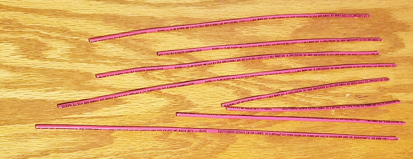
These are the spark plug harness wires as initially cut to length. A light wipe with acetone cleanly removed all the printing. I then spent
the time to carefully straighten the wires before starting to form them into position.
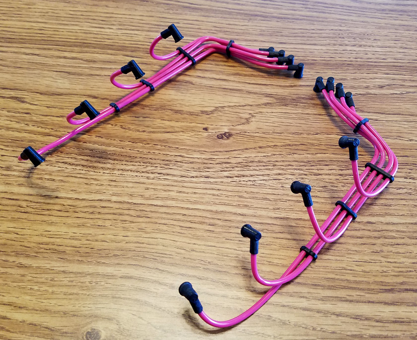
The finished harnesses look far better than I could have imagined as I was trying to bend them into shape. A drop of superglue
every place the wire touches plastic holds them securely in place.
The hardware kit came with a 12 volt gearhead motor which assumes the role of the starter motor. It also came with a speed controller, a wall type power supply and several connectors.
The final mechanical part of the build was mounting the gearhead motor with its drive gear to its mounting block and then attaching that at the corner of the oil pan to the block.
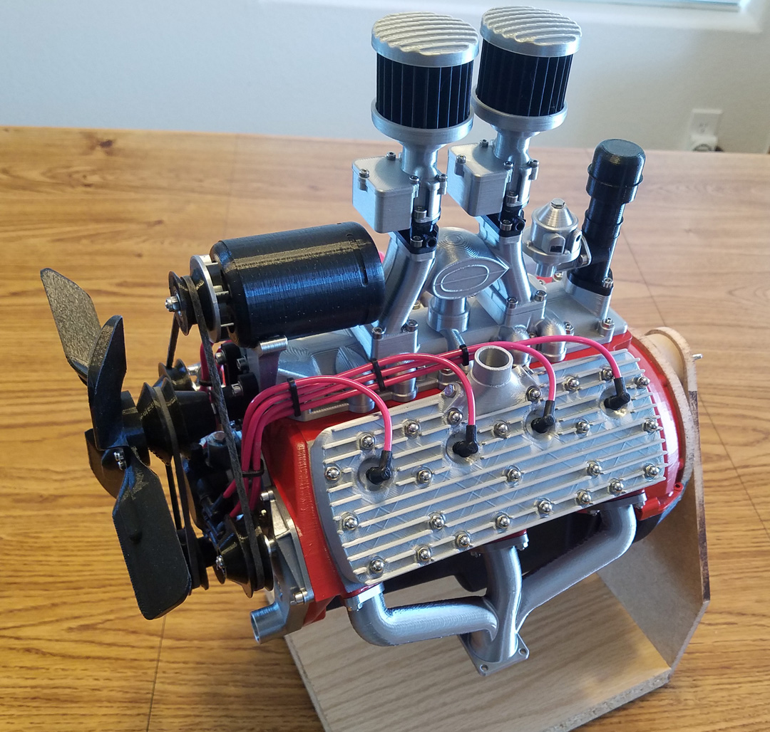
And here is the completed engine!
Control Box:
The hardware kit came with a wall plug-in type power supply, a speed controller board, and several connectors to power the motor. I wanted something a little more elaborate. On Thingiverse I found a box designed by Casey Clark (screen name twistclark), specifically to hold the variable speed controller from this engine. It is in the shape of a 6 volt battery which adds a nice touch. Thank you Casey!
In addition to running from the wall power supply, I would like to be able to run it from a portable power pack designed to recharge cell phones. The only problem is that these are all 5 volt and use a USB type connector. I have a boost module left over from a previous project that will output a higher voltage than the input. It was easy to adjust it to convert 5 volts DC to 12 volts DC. It can supply much higher current than the engine requires and is a perfect fit.
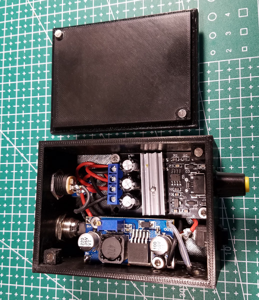
I originally printed the battery box as designed, and my speed controller fit perfectly. I then started experimenting with adding the boost module and additional connectors and ended up designing a box from scratch the exact size of the original, so the battery shaped lid will still fit. The new box has mounting provisions for 3 circuit boards: the speed controller, the boost converter, and a tiny board, approximately 1/2 inch square, which mounts a micro USB connector and provides easy mounting and connecting. The box also holds an on/off switch and 3 connectors.
I drew up a connection diagram, and the only components needed are the 3 boards, 3 input and output connectors, a power switch, and a diode. The diode prevents the wall power supply from back-feeding power into the output of the boost converter.
After I completed the box and everything worked functionally, I was not satisfied with the lid which merely sat passively on the box, so of course, I attached a pair of magnets to the box and another pair to the cover. To do this, I printed a pair of 6mm cubes with a magnet socket in one side. I glued these inside the box at two corners the correct distance down from the top. A pair of magnets surface glued to the cover completed the mod.
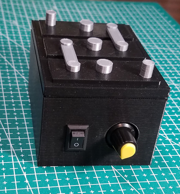
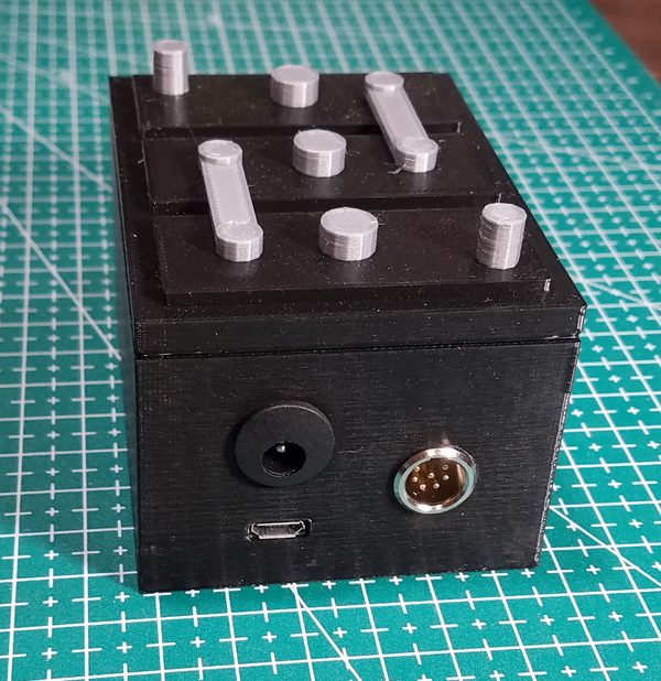
The redesigned base box holds all the additional components I desired. On the left, the front of the box has a power switch and the speed
control knob. In the center, the rear contains the 12 volt connector, a 5 volt micro USB below it, and a motor power connector on the right.
(That is a much more elaborate connector than required, but it is what I had.)
The picture on the right shows the added magnets.
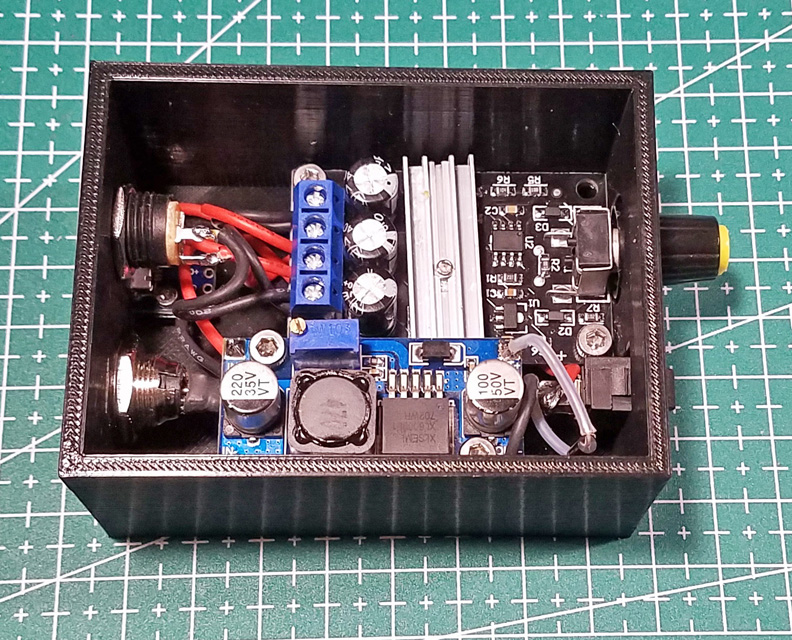
It's a tight fit inside the box, but by mounting the controller low and the boost module high it fit nicely. On the left rear, near the base of the box is the tiny USB
connector board. The upper right is the supplied speed controller, and the near side is the boost converter.
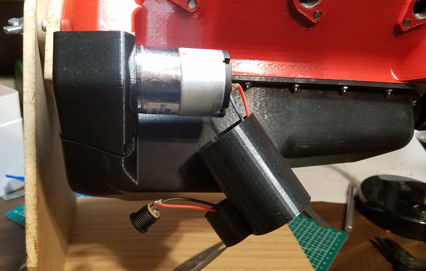
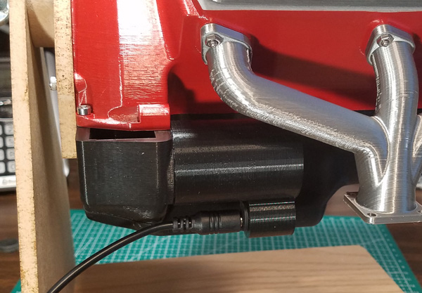
The picture on the left shows what the uncovered motor looks like, as well as the ease of wiring the motor and connector. The right shows the cover in place
and the connector plugged in to power the motor. I used a turn of electrical tape on the connector and two layers on the motor and all the parts pressed
together quite firmly.
The hardware kit came with a wall plug-in type power supply, a speed controller board, and several connectors to power the motor. I wanted something a little more elaborate. On Thingiverse I found a box designed by Casey Clark (screen name twistclark), specifically to hold the variable speed controller from this engine. It is in the shape of a 6 volt battery which adds a nice touch. Thank you Casey!
In addition to running from the wall power supply, I would like to be able to run it from a portable power pack designed to recharge cell phones. The only problem is that these are all 5 volt and use a USB type connector. I have a boost module left over from a previous project that will output a higher voltage than the input. It was easy to adjust it to convert 5 volts DC to 12 volts DC. It can supply much higher current than the engine requires and is a perfect fit.
I originally printed the battery box as designed, and my speed controller fit perfectly. I then started experimenting with adding the boost module and additional connectors and ended up designing a box from scratch the exact size of the original, so the battery shaped lid will still fit. The new box has mounting provisions for 3 circuit boards: the speed controller, the boost converter, and a tiny board, approximately 1/2 inch square, which mounts a micro USB connector and provides easy mounting and connecting. The box also holds an on/off switch and 3 connectors.
I drew up a connection diagram, and the only components needed are the 3 boards, 3 input and output connectors, a power switch, and a diode. The diode prevents the wall power supply from back-feeding power into the output of the boost converter.
After I completed the box and everything worked functionally, I was not satisfied with the lid which merely sat passively on the box, so of course, I attached a pair of magnets to the box and another pair to the cover. To do this, I printed a pair of 6mm cubes with a magnet socket in one side. I glued these inside the box at two corners the correct distance down from the top. A pair of magnets surface glued to the cover completed the mod.
The redesigned base box holds all the additional components I desired. On the left, the front of the box has a power switch and the speed
control knob. In the center, the rear contains the 12 volt connector, a 5 volt micro USB below it, and a motor power connector on the right.
(That is a much more elaborate connector than required, but it is what I had.)
The picture on the right shows the added magnets.
It's a tight fit inside the box, but by mounting the controller low and the boost module high it fit nicely. On the left rear, near the base of the box is the tiny USB
connector board. The upper right is the supplied speed controller, and the near side is the boost converter.
A late
discovery:
The latest improvement was created by a discovery I should have made earlier. During the build, I kept thinking that the raw drive motor really needed something to disguise it, but put off any action till later. Then in looking again at Eric's model I noticed that he had a cover over the motor. I looked carefully at the list of files supplied, and there was a starter cover. I had missed it completely as it was not on the Printed Parts List in the manual, and it did not jump out at me from the list of the 84 supplied files.
Needless to say I immediately printed it and it is really nice. Not only does it cover the bright metal motor, but in the replica starter solenoid is room for the extra connector supplied in the kit. This not only makes the general appearance much better, but it eliminates any hanging wires until you plug in a cable to run it. The cover is long enough that I could leave enough wire to make easy connections and the excess easily fit in the end.
The picture on the left shows what the uncovered motor looks like, as well as the ease of wiring the motor and connector. The right shows the cover in place
and the connector plugged in to power the motor. I used a turn of electrical tape on the connector and two layers on the motor and all the parts pressed
together quite firmly.
Engine Stand:
The hardware kit for the engine stand is still sold out, so I am building one semi "from scratch". I decided to use all of Eric's design except the head which supports the engine and allows it to be rotated. I designed the head using a hollow pivot shaft instead of the solid. Full size stands are made both ways. In order to build the base, I had to locate some 3/4 inch square aluminum tubing with a 1/16 wall thickness. There were a number of metal supply houses which could supply it, but I found that Home Depot carries both 3 and 4 foot lengths in their hobby metal section. I picked up a 4 foot section, as the 3 would only allow a fraction of an inch to spare, much of which would be used by the saw blade width. Besides they were out of the 3 foot. I paid a small fortune for it, but I had it in my hands an hour after I decided to go over and buy it. I printed all the needed parts per the manual's guidance, and found that I had all the metric hardware I needed. While at Home Depot I picked up several bags containing the hex head sheet metal screws and some stainless washers to fit and a couple other small hardware items.
For the wheels on the forward end swivel casters, the design calls out for ball bearings. I was not going to buy a pack of 10 just to get 2, so I decided to 3D print a pair of wheels. Then, just in case, I checked my supply drawer in my shop and found that the extra bearings I bought several years ago to replace the blade guides on my bandsaw when they fail were the exact part number called out. I now have ball bearing front wheels.
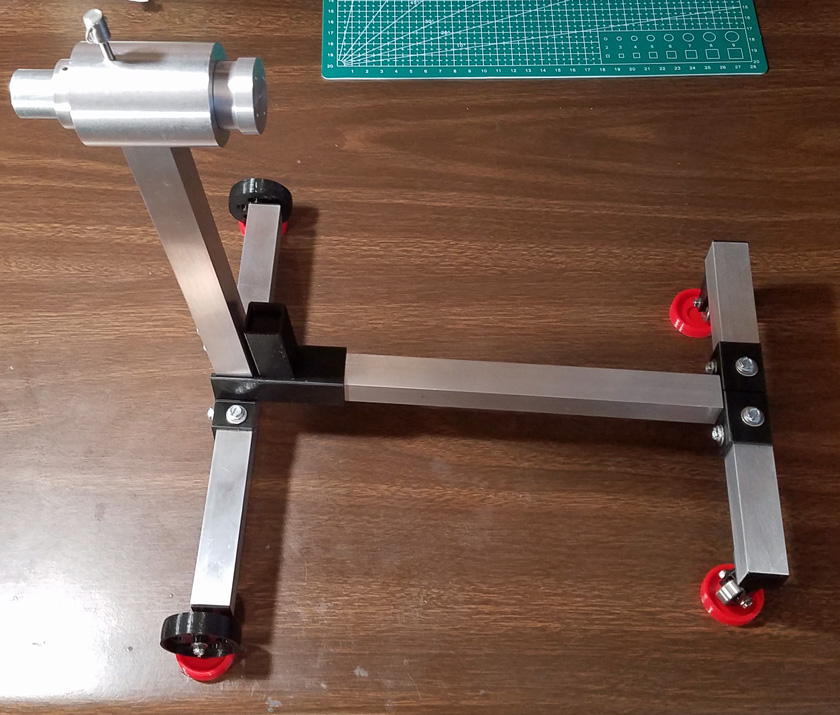
Here is the base frame built to Eric's specifications. The head unit is my design and is partially complete here.
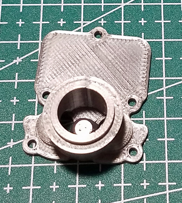
The head unit I designed consists of a hollow pivot shaft, a length of 1/2 electrical conduit (EMT). This rides in a snug fitting hole of the main housing with a spacer on each end to constrain it. Inside the end of the shaft and one of the spacers is a part with a shaft which fits tightly in the tubing. It has a flange on the end which mounts the flat attachment plate.
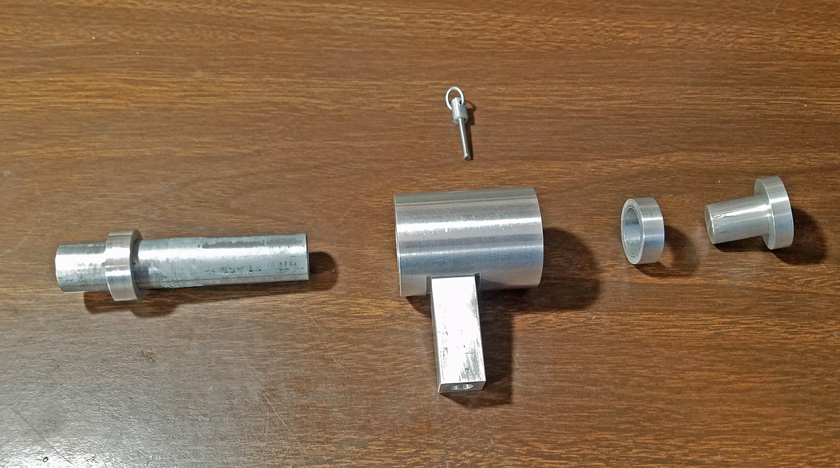
These are the components of the head assembly. On the left is the pivot tube with one of the spacers installed. Next is the main housing. This has
a hole through it to fit the pivot tube, and a square piece which fits in the top of the vertical square tube. The spacer on the right fits
flush to the end of the pivot tube and the mounting plug on the end fits tightly into the tube. 3 screws pass through the spacer and the pivot
tube and are threaded into the plug. The pin on the top drops in a hole on the top of the housing and through one of the 12 holes in the tube
to allow the engine to be held at 30 degree intervals. The pin is a 1/8 inch dowel pin with a 3D printed end attached.
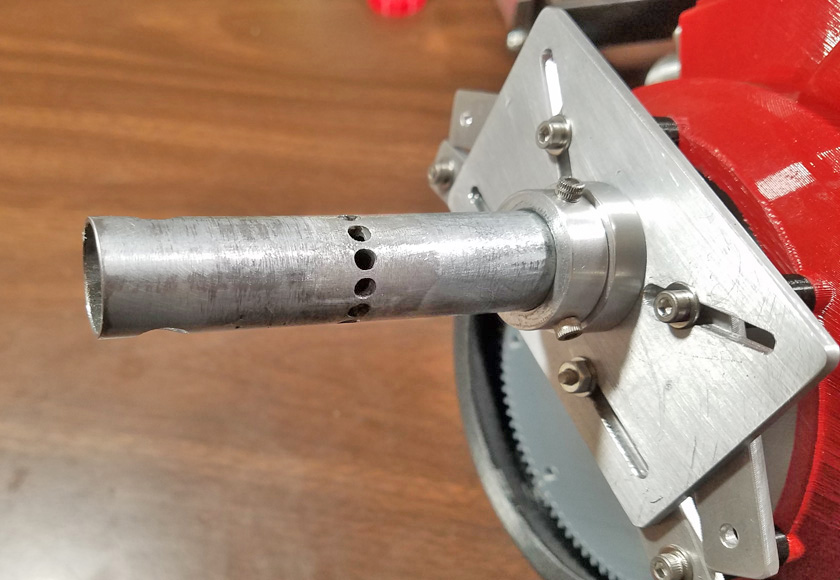
The holes have been drilled in the pivot tube. On the right you can see the head of the mounting plug attached to the mounting plate. It
is inserted flush to the end of the tube. The 3 screws around the spacer thread into the plug.
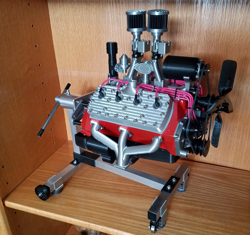
And here we see the completed stand holding the engine on the display shelf I have for it in my Living Room. It is sitting on 4 rubber
pads on printed clips to prevent it from rolling off the shelf.
I made a second vertical tube 2 1/2 inches shorter than the original (good thing I bought the 4 feet of square tubing!). This lowers the
engine to fit my display space and makes a more compact display unit. I am keeping the longer tube for possible substitution later.
Conclusion:
This has been a totally enjoyable project and has provided an immense degree of satisfaction upon its completion.
I cannot thank Eric Harroll enough for the un-imaginable amount of time it must have taken him to research, measure, examine, and actually design the multitude of parts needed to complete this engine, and then to write an excellent manual, just so he can give it all away to make it possible for someone like me to build it. THANK YOU!
Attributions:
Here are the official Thingiverse attribution plaques giving thanks and credit to Eric (ericthepoolboy) and Casey (twistclark) for their outstanding designs:


The original Ford Flat Head V8 Control Box by twistclark can be found at: https://www.thingiverse.com/thing:2977930
GO BACK TO "Machine Shop Mods"
R. S. Mason November 2019