3D Printer
Background
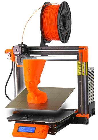
Early this year (2018) I was thinking seriously about getting a 3D printer. I have been eying them for years, and my interest peaked when my son David decided to get one! After debating with myself I finally said to myself "if not now, then when?" and decided to bite the bullet. David had researched various brands and came to the conclusion that the Prusa Original i3 printers were the best in their price range. I started researching and came to the same conclusion. The MK2 version of this printer has won many awards and pretty much universal praise from reviewers. In late 2017 they came out with a new model, the MK3, which has pretty much everything the MK2 does with a large number of additions and improvements. Unfortunately the initial response to their bringing the new model to market totally overwhelmed the company and they rapidly developed a long backorder list. Early on, the delivery time was about 3 months, but we both felt the product was worth the wait. I placed my order the end of January, David placed his about a month later. I actually received mine in about 2 1/2 months, he received his in about 2 months. The company has been working very hard to eliminate the backlog.
We each ordered ours in kit form as that is the best way to really get familiar with the machine. It also saves about $250.
Prusa Research is an interesting company: Josef Prusa of Prague, Czech Republic started working with 3D printers about 9 years ago, and was very active in the "RepRap" project of developing 3D printer hardware and software as open source. This means that the plans, software, assembly methods, etc. are totally open to the public with no fees required to use the data. Josef was so successful at this that he developed one of the best machines of the time and started his own company. He is a very strong advocate of the open source movement and everything he designs and sells is published for all to use. As a result there are about 100 clones of his machines on the market, some even advertising Prusa i3 in the name of their units. So far, the general opinion of the experts is that even though all his design details are available to them, not one of the clones has yet succeeded in reaching the quality and feature level of his machines and quality of the prints it produces.
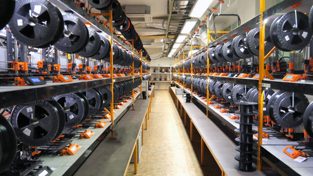
This is looking down one aisle of Prusa's printer farm. Each one of the roughly 300 printers can print all the
plastic parts for one printer in approximately a day - every day!
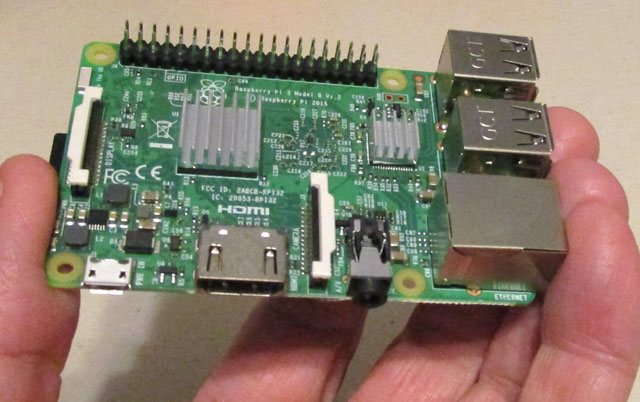
The Raspberry Pi computer is credit card sized and costs about $35. It runs a full implementation of Linux
and is capable of running a fully graphic windowing based system. It has built in WiFi, 4 USB ports, Ethernet
and HDMI ports.It is an extremely powerful computer for its size. In this application it.runs OctoPi from
a micro SD card.
The OctoPrint website has a lot of information on setting up the system, but I got my best help from a couple of Youtube videos showing the setup process step by step. It really was pretty easy. When I connected it all in a breadboard fashion it worked the first time. I had a little trouble getting a webcam to work, but when I took the one off my main system and tried it it worked the first time. I ran a couple of test parts controlling it totally from my desktop computer and it all worked well. The first time-lapse failed because I neglected to check a box, but once I realized that, they all have been working great.
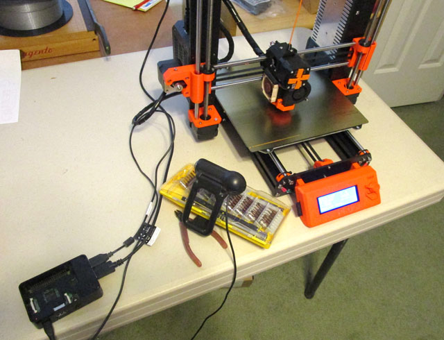
To try out everything after installing all the required software and connecting it all, I spread the parts out on the
table with loose cords between them. I jury-rigged the webcam from my main computer so it would point at
the build area. It all went very smoothly and worked well.
Early this year (2018) I was thinking seriously about getting a 3D printer. I have been eying them for years, and my interest peaked when my son David decided to get one! After debating with myself I finally said to myself "if not now, then when?" and decided to bite the bullet. David had researched various brands and came to the conclusion that the Prusa Original i3 printers were the best in their price range. I started researching and came to the same conclusion. The MK2 version of this printer has won many awards and pretty much universal praise from reviewers. In late 2017 they came out with a new model, the MK3, which has pretty much everything the MK2 does with a large number of additions and improvements. Unfortunately the initial response to their bringing the new model to market totally overwhelmed the company and they rapidly developed a long backorder list. Early on, the delivery time was about 3 months, but we both felt the product was worth the wait. I placed my order the end of January, David placed his about a month later. I actually received mine in about 2 1/2 months, he received his in about 2 months. The company has been working very hard to eliminate the backlog.
We each ordered ours in kit form as that is the best way to really get familiar with the machine. It also saves about $250.
Prusa Research is an interesting company: Josef Prusa of Prague, Czech Republic started working with 3D printers about 9 years ago, and was very active in the "RepRap" project of developing 3D printer hardware and software as open source. This means that the plans, software, assembly methods, etc. are totally open to the public with no fees required to use the data. Josef was so successful at this that he developed one of the best machines of the time and started his own company. He is a very strong advocate of the open source movement and everything he designs and sells is published for all to use. As a result there are about 100 clones of his machines on the market, some even advertising Prusa i3 in the name of their units. So far, the general opinion of the experts is that even though all his design details are available to them, not one of the clones has yet succeeded in reaching the quality and feature level of his machines and quality of the prints it produces.
Prusa is their own best
customer. They have a printer farm
consisting of over 300 MK2 and MK3 printers running 24/7 producing all
the printed parts used in their machines. They state that one
machine can produce all the parts for one printer in about 27
hours. They are a very customer oriented outfit, constantly
improving their machines and offering upgrades to the latest
configuration to their previous customers. The upgrade costs are
quite nominal. One of the results of printing their
plastic parts
rather than injection molding them, other than the tremendously lower
tooling costs, is
that if a change is needed, the time to put it into production is very
short - upgrade the computer design file and feed it to the printer
farm. The new parts are incorporated in a matter of days, not
months!
This is looking down one aisle of Prusa's printer farm. Each one of the roughly 300 printers can print all the
plastic parts for one printer in approximately a day - every day!
A quick "how it
works" description
There are a number of processes in use today to do 3D printing. Some use patterns of light or a laser to harden a resin into desired patterns, some use a powder and similarly use a laser to selectively fuse it. There are many industrial variations, some even printing in metal, but the most common and almost the only method used by hobbyists and small businesses is FDM (Fused Deposition Modeling), also called FFF (*Fused Filament Fabrication), the type discussed here where plastic is heated and extruded through a fine nozzle, depositing plastic in areas where it hardens into the final print. The one thing that is common with all the types of 3D printers is that they do this hardening or adding of material one thin layer at a time. By having access to all parts of each "slice" as the part is built up, some incredibly complex forms can be created. Shapes that can be made by no other means can be created. The rest of this article will be only discussing the FDM (or FFF) design which is what our Prusa printers are.
* The term FFF was created by the RepRap project when a company claimed to have a trademark on the term FDM. Rather than risk future legal problems, they invented the FFF term to use instead.
Building my printer
To see an overview of the kit assembly process, please CLICK HERE
Initial things I made:
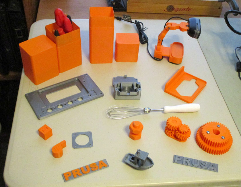
Some of my 3D prints: Top row l to r: 3D printer tool case, glasses (or ?) case, portable webcam stand. 2nd row: instrument front panel,
meter cam case and cover, Raspberry Pi holder. 3rd row: 20mm calibration cube, replacement handle for a wisk. 4th row: whistle, stepper motor
spacer, nut and bolt, multistage herringbone gear transmission, gears for my lathe to allow metric threading. Bottom row: fancy Prusa badge,
Benchy, plain Prusa badge. There are several more which are already installed or in use and not available for a table presentation.
As soon as the printer was complete and adjusted, I started making things. The first few items were pretty rough, but once I figured out how to set the initial layer height, they started coming out beautifully! The very first print was a PRUSA badge which was included on the supplied SD card. After getting it to print well, I stopped it when the base was completed in silver plastic, changed the filament to orange, and completed printing the name. This resulted in a nice 2 color print. I also printed the mandatory "Benchy" print which is a small tugboat which serves as a benchmark print for 3D printing. It contains overhangs, bridges, various surfaces, and several small details allowing users to compare many aspects of their printer's performance. It is pretty much a standard of comparison in the 3D community. They also supplied the files for a whistle which I printed (it is VERY loud!)
3d CAD programs:
FreeCAD
As soon as I decided to order the printer, I started taking on-line tutorials on 3D CAD programs, as I have never used one before. Of course the "3D" means it is dealing with solid objects as opposed to the flat images (like on paper) of 2D images. The "CAD" stands for Computer Aided Design. I have used a couple 2D CAD programs for many years, so I at least had a concept of what was needed. I started with a series on FreeCAD which as the name suggests is a totally free CAD program. It taught me many aspects of 3D design and I reached the minimal level of competency to be able to design items starting from scratch. Even though it is quite well regarded as an "enthusiast's" program (they do not recommend it for commercial use at this time), I found it crashed far too often, and at the most awkward times and I gave up on it.
Onshape
Next I found OnShape which is a professional program hosted totally on-line. You operate it through a browser and all your files are kept on their server. As long as you agree to allow all your generated files to be available to their other users, they allow free use of the program. With what I had learned from FreeCAD, the learning curve was not too bad, and I "mastered" it fairly quickly by taking a series of video lessons. This is an excellent program and I really do not have any complaints with it. It is fast, it is capable, it is relatively easy to use, and it is free! I very well could have stayed exclusively with OnShape.
Fusion 360
The majority of users I have been exposed to on-line seem to like Fusion 360 which is a program by AutoDesk, maker of AutoCAD which is the granddaddy of all CAD programs and very well respected. I thought I should try Fusion 360 as well. AutoDesk has made this program free in the form of 3 year licenses to students and educators. They also offer 1 year licenses to "startups" and "enthusiasts" provided their income from this is less than $100,000 a year. I applied for and received a license. I found a series of Youtube lessons which were very well presented by Paul McWhorter, and went through all 13 lessons. I have now settled on Fusion 360 for all my 3D designs, but if anything should happen to prevent me from continuing, I could readily make do with OnShape.
OpenSCAD
The final 3D CAD program I have somewhat learned is OpenSCAD. This uses a totally different approach in 3D design from most programs which are visually based. With them, you start drawing in 2D, drawing lines, circles, arcs, etc., then using their tools you convert it to 3D using extrusion, rotation, sweeps, etc. All your actions are immediately shown in a 3D rendering, which you can rotate and zoom to view from any angle and distance. OpenSCAD is a script driven program. In a text editor you specify everything, for example, to create a cylinder of a certain diameter and height, at a certain location from the origin (where X, Y, and Z are all = 0), and at what rotational angle. You can do the same for spheres and cubes along with several other items. You combine these objects to either add to the main item, subtract, such as holes, or more complex combinations like where they do or do not intersect, etc. When you want to see the result of your script, you need to tell the program to calculate the results and show them as an image. Only now do you know if your script works the way you intend. I personally find this approach much more difficult than the normal visual types, but there are a several advantages to OpenSCAD:
Several of the printed objects above are the learning examples from the tutorials on Fusion 360. The tool and glasses cases are really one design which was done parametrically meaning that many of the dimensions are set up as variables which can be defined as constants or functions of other variables. These are all listed on one form. The program is designed so that if you change the value of any parameter, it totally re-calculates the drawing to show its new form. For these two cases I merely changed the length, width, height of the base and lid, and the wall thickness. It then produced the two cases without any other design changes. The lid is a snug slip fit on the base. The nut and bolt and the herringbone gear transmission were also class examples.
I downloaded the *webcam stand and the *calibration cube from Thingiverse, Prusa supplied the files for the Prusa badges, whistle, and Benchy. I designed the rest from scratch using Fusion 360. It is really great to have a design thought, draw it on the computer, and in a matter of minutes to hours depending on the complexity, have the item in your hands!
I installed 2 of my metercam housings on my solar and main electrical meters, which already had less well protected cameras (see My Solar, Metercams for details). I expect these housings will keep the cameras from malfunctioning even in heavy rains.
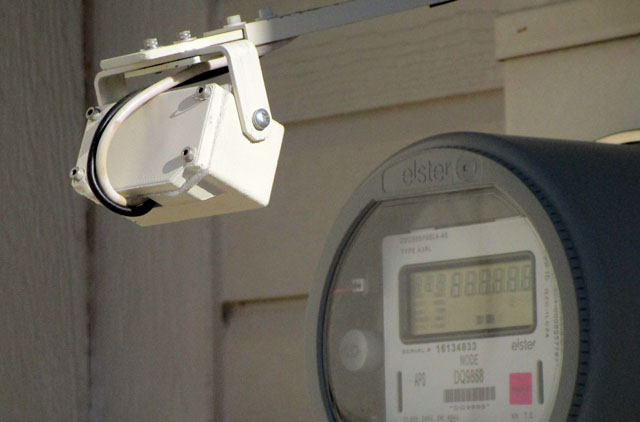
My metercams are now housed in 3D printed protective housings. Yes, I painted them to get the color I want.
Printer Enhancements:
OctoPrint
After my first couple weeks of getting familiar with the printer and learning how to consistently make good prints, I started implementing several improvements. The major improvement was to implement OctoPrint and OctoPi. OctoPrint is a software program which will run on practically any computer attached to the 3D printer and which talks to its controller to allow pretty much total control of the printer. OctoPi is a special implementation to run on the Raspberry Pi computer.
Using a Raspberry Pi computer and OctoPi is by far the most common implementation, and the one I chose, with the Pi attached to the printer using a USB cord, It is connected to a WiFi network and is in communication with a desktop or laptop computer using only a browser, as the OctoPrint contains its own web server. Once you start a printing job using OctoPrint, the entire task is transferred to the Raspberry Pi and it continues independently from that point on. This has the tremendous advantage over merely connecting the main computer to the printer that once the print is started it is immune to network failures, operator error, or problems with the main computer. This can be significant when running a print that takes many hours.
There are a number of processes in use today to do 3D printing. Some use patterns of light or a laser to harden a resin into desired patterns, some use a powder and similarly use a laser to selectively fuse it. There are many industrial variations, some even printing in metal, but the most common and almost the only method used by hobbyists and small businesses is FDM (Fused Deposition Modeling), also called FFF (*Fused Filament Fabrication), the type discussed here where plastic is heated and extruded through a fine nozzle, depositing plastic in areas where it hardens into the final print. The one thing that is common with all the types of 3D printers is that they do this hardening or adding of material one thin layer at a time. By having access to all parts of each "slice" as the part is built up, some incredibly complex forms can be created. Shapes that can be made by no other means can be created. The rest of this article will be only discussing the FDM (or FFF) design which is what our Prusa printers are.
* The term FFF was created by the RepRap project when a company claimed to have a trademark on the term FDM. Rather than risk future legal problems, they invented the FFF term to use instead.
Building my printer
To see an overview of the kit assembly process, please CLICK HERE
Initial things I made:
Some of my 3D prints: Top row l to r: 3D printer tool case, glasses (or ?) case, portable webcam stand. 2nd row: instrument front panel,
meter cam case and cover, Raspberry Pi holder. 3rd row: 20mm calibration cube, replacement handle for a wisk. 4th row: whistle, stepper motor
spacer, nut and bolt, multistage herringbone gear transmission, gears for my lathe to allow metric threading. Bottom row: fancy Prusa badge,
Benchy, plain Prusa badge. There are several more which are already installed or in use and not available for a table presentation.
As soon as the printer was complete and adjusted, I started making things. The first few items were pretty rough, but once I figured out how to set the initial layer height, they started coming out beautifully! The very first print was a PRUSA badge which was included on the supplied SD card. After getting it to print well, I stopped it when the base was completed in silver plastic, changed the filament to orange, and completed printing the name. This resulted in a nice 2 color print. I also printed the mandatory "Benchy" print which is a small tugboat which serves as a benchmark print for 3D printing. It contains overhangs, bridges, various surfaces, and several small details allowing users to compare many aspects of their printer's performance. It is pretty much a standard of comparison in the 3D community. They also supplied the files for a whistle which I printed (it is VERY loud!)
3d CAD programs:
FreeCAD
As soon as I decided to order the printer, I started taking on-line tutorials on 3D CAD programs, as I have never used one before. Of course the "3D" means it is dealing with solid objects as opposed to the flat images (like on paper) of 2D images. The "CAD" stands for Computer Aided Design. I have used a couple 2D CAD programs for many years, so I at least had a concept of what was needed. I started with a series on FreeCAD which as the name suggests is a totally free CAD program. It taught me many aspects of 3D design and I reached the minimal level of competency to be able to design items starting from scratch. Even though it is quite well regarded as an "enthusiast's" program (they do not recommend it for commercial use at this time), I found it crashed far too often, and at the most awkward times and I gave up on it.
Onshape
Next I found OnShape which is a professional program hosted totally on-line. You operate it through a browser and all your files are kept on their server. As long as you agree to allow all your generated files to be available to their other users, they allow free use of the program. With what I had learned from FreeCAD, the learning curve was not too bad, and I "mastered" it fairly quickly by taking a series of video lessons. This is an excellent program and I really do not have any complaints with it. It is fast, it is capable, it is relatively easy to use, and it is free! I very well could have stayed exclusively with OnShape.
Fusion 360
The majority of users I have been exposed to on-line seem to like Fusion 360 which is a program by AutoDesk, maker of AutoCAD which is the granddaddy of all CAD programs and very well respected. I thought I should try Fusion 360 as well. AutoDesk has made this program free in the form of 3 year licenses to students and educators. They also offer 1 year licenses to "startups" and "enthusiasts" provided their income from this is less than $100,000 a year. I applied for and received a license. I found a series of Youtube lessons which were very well presented by Paul McWhorter, and went through all 13 lessons. I have now settled on Fusion 360 for all my 3D designs, but if anything should happen to prevent me from continuing, I could readily make do with OnShape.
OpenSCAD
The final 3D CAD program I have somewhat learned is OpenSCAD. This uses a totally different approach in 3D design from most programs which are visually based. With them, you start drawing in 2D, drawing lines, circles, arcs, etc., then using their tools you convert it to 3D using extrusion, rotation, sweeps, etc. All your actions are immediately shown in a 3D rendering, which you can rotate and zoom to view from any angle and distance. OpenSCAD is a script driven program. In a text editor you specify everything, for example, to create a cylinder of a certain diameter and height, at a certain location from the origin (where X, Y, and Z are all = 0), and at what rotational angle. You can do the same for spheres and cubes along with several other items. You combine these objects to either add to the main item, subtract, such as holes, or more complex combinations like where they do or do not intersect, etc. When you want to see the result of your script, you need to tell the program to calculate the results and show them as an image. Only now do you know if your script works the way you intend. I personally find this approach much more difficult than the normal visual types, but there are a several advantages to OpenSCAD:
- This is the only program I have found where you can easily import an STL file and directly edit it (with limitations). STL files are the output files from most 3D CAD programs, and are all that many of the authors on public sharing sites like Thingiverse offer.
- This is
the "official" CAD program of Thingiverse, an on-line library of over a
million objects designed by individuals or companies, and placed for
anyone to use without charge. Some of their offerings include
source files for OpenSCAD, most do not.
- This
program is open source and is totally free for anyone to use without
restrictions i.e. making your designs public, limiting the income you
can make, relying on a company to not change policies, etc
Several of the printed objects above are the learning examples from the tutorials on Fusion 360. The tool and glasses cases are really one design which was done parametrically meaning that many of the dimensions are set up as variables which can be defined as constants or functions of other variables. These are all listed on one form. The program is designed so that if you change the value of any parameter, it totally re-calculates the drawing to show its new form. For these two cases I merely changed the length, width, height of the base and lid, and the wall thickness. It then produced the two cases without any other design changes. The lid is a snug slip fit on the base. The nut and bolt and the herringbone gear transmission were also class examples.
I downloaded the *webcam stand and the *calibration cube from Thingiverse, Prusa supplied the files for the Prusa badges, whistle, and Benchy. I designed the rest from scratch using Fusion 360. It is really great to have a design thought, draw it on the computer, and in a matter of minutes to hours depending on the complexity, have the item in your hands!
I installed 2 of my metercam housings on my solar and main electrical meters, which already had less well protected cameras (see My Solar, Metercams for details). I expect these housings will keep the cameras from malfunctioning even in heavy rains.
My metercams are now housed in 3D printed protective housings. Yes, I painted them to get the color I want.
Printer Enhancements:
OctoPrint
After my first couple weeks of getting familiar with the printer and learning how to consistently make good prints, I started implementing several improvements. The major improvement was to implement OctoPrint and OctoPi. OctoPrint is a software program which will run on practically any computer attached to the 3D printer and which talks to its controller to allow pretty much total control of the printer. OctoPi is a special implementation to run on the Raspberry Pi computer.
Using a Raspberry Pi computer and OctoPi is by far the most common implementation, and the one I chose, with the Pi attached to the printer using a USB cord, It is connected to a WiFi network and is in communication with a desktop or laptop computer using only a browser, as the OctoPrint contains its own web server. Once you start a printing job using OctoPrint, the entire task is transferred to the Raspberry Pi and it continues independently from that point on. This has the tremendous advantage over merely connecting the main computer to the printer that once the print is started it is immune to network failures, operator error, or problems with the main computer. This can be significant when running a print that takes many hours.
The Raspberry Pi computer is credit card sized and costs about $35. It runs a full implementation of Linux
and is capable of running a fully graphic windowing based system. It has built in WiFi, 4 USB ports, Ethernet
and HDMI ports.It is an extremely powerful computer for its size. In this application it.runs OctoPi from
a micro SD card.
The OctoPrint website has a lot of information on setting up the system, but I got my best help from a couple of Youtube videos showing the setup process step by step. It really was pretty easy. When I connected it all in a breadboard fashion it worked the first time. I had a little trouble getting a webcam to work, but when I took the one off my main system and tried it it worked the first time. I ran a couple of test parts controlling it totally from my desktop computer and it all worked well. The first time-lapse failed because I neglected to check a box, but once I realized that, they all have been working great.
To try out everything after installing all the required software and connecting it all, I spread the parts out on the
table with loose cords between them. I jury-rigged the webcam from my main computer so it would point at
the build area. It all went very smoothly and worked well.
Once it all worked correctly, I
went to
work to package it neatly on the machine itself. I designed a
shelf type mount for the Pi that bolted to the side of the frame
rail. I then found a webcam support on Thingiverse and printed
all the parts for it. It mounts a specific webcam on the end of
several adjustable links, allowing you to set the height and angle for
best viewing of the printing process. This worked very well, but
required the camera to be set on the table and pointed each time, and
was often in the way. I then found a mount for a webcam that
attached to the end of the Z axis gantry. This would raise the
camera as the print was built up higher. It also kept the camera
within the existing outline of the printer. I built the
downloaded mount and liked the idea, but not the specific mount.
I decided exactly where I wanted the camera to mount and designed a
mount to hold it there. When the Pi and webcam mounting were
complete they looked good and worked well. I'll go with both of
them at least for the time being.
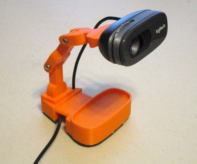
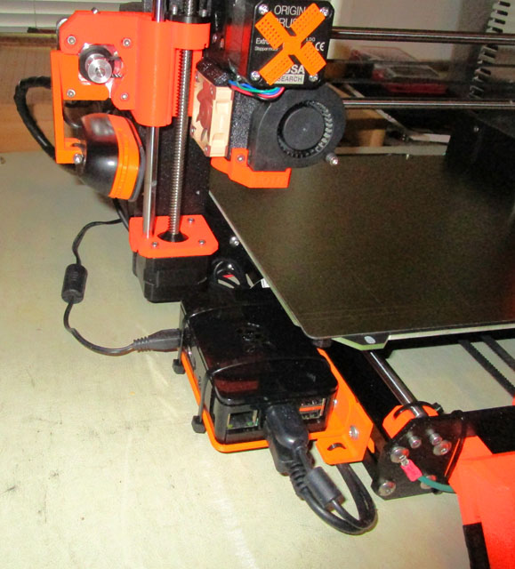
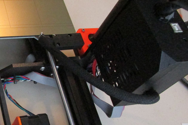
On the left is the adjustable *webcam mount I first made. The webcam was inexpensive and I bought 2. There is a modification to it which allows
manual focusing, which I feel is a must. The right picture shows the Raspberry Pi mounted to the frame and the other webcam mounted to the
Z axis. It is less flexible getting the angle you may desire, but it is permanently mounted and always there. It also does not make the outline of
the printer any larger. If I want a different angle, I will use the portable camera. I chose the same model camera for both so I would not have to
reconfigure the Pi when I change them. This shot also shows an earlier modification: the small windmill on the extruder stepper motor. This gives
a great visual indication of just how fast the extruder is feeding filament at any given time. It snaps to the back end of the motor shaft using a
powerful magnet super glued to the windmill print.
The completed box has a switch, two outlets, and a power input connector. The power cable on the left plugs
into the normal power cord connector on the printer. The small cable brings the signals from the Raspberry Pi.
The only component inside the case is the solid state relay.
Fully installed, the box looks like it is an original part of the printer.
The box mounts to two threaded inserts in the power supply on the side (as looking at the front of the printer) and one
on the back which anchors a long stabilizing arm. The three screws hold the box very securely.
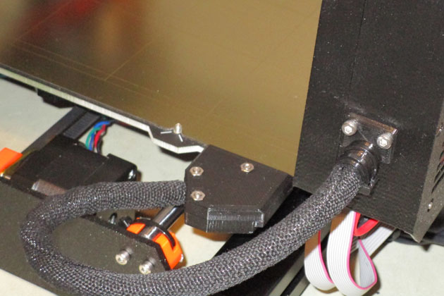
The 90 degree cable block on the left causes the cable to be pulled at a sharper angle than I like. The 60 degree exit block on the right solves that problem and still prevents
the cable loop from extending as far to the back allowing a smaller enclosure than the original setup. The strain relief on the control box keeps the cable secure and level.
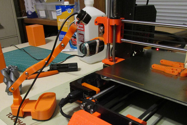
I made what I call my "gooseneck camera" by printing several extra forks from the adjustable webcam mount
shown above. I mounted a camera designed as an accessory backup camera for a car (except this one is for the
front of the car) on the top and connected it to a spare channel of my security system. I can now keep tabs
on my prints in other parts of the house or even on my cell phone when I am away from home if I desire.
On the left is the adjustable *webcam mount I first made. The webcam was inexpensive and I bought 2. There is a modification to it which allows
manual focusing, which I feel is a must. The right picture shows the Raspberry Pi mounted to the frame and the other webcam mounted to the
Z axis. It is less flexible getting the angle you may desire, but it is permanently mounted and always there. It also does not make the outline of
the printer any larger. If I want a different angle, I will use the portable camera. I chose the same model camera for both so I would not have to
reconfigure the Pi when I change them. This shot also shows an earlier modification: the small windmill on the extruder stepper motor. This gives
a great visual indication of just how fast the extruder is feeding filament at any given time. It snaps to the back end of the motor shaft using a
powerful magnet super glued to the windmill print.
Using OctoPrint is a joy. I
design
(or download) the original file in the normal manner, then run it
through a slicer, also normally. A slicer is a program which
takes
the completed design and looks at cross sections one slice at a
time. Each slice is a layer of printed plastic. The slicer
is where you define all your printing variables such as temperature,
speed, layer height, and many other less obvious parameters. Once
it is sliced, the program writes a file of G-code. This defines
every X, Y, Z, and extruder value for every tiny move. It is not
unusual for a G-code file to have 500,000 lines or more. This
file is then ready to send to the printer. Before OctoPrint, you
either removed the SD card from the printer, copied your file to it on
your computer, then replaced the SD card in the printer, or you connected
your computer directly to the printer via USB or WiFi.
Connecting to your computer is handier, but very vulnerable to problems
with the network, computer, or even the operator doing something which
interferes with it, as data is constantly going both ways for the full
duration of the print. It is very
disappointing when the print fails, and you are 6
hours into a 7 hour print! Using the SD card method is much more
robust, as the printer depends only on its internal circuits, but is is
much less convenient to use.
Using OctoPrint, you have the convenience of doing all the file handling on your desktop computer, but once it is sent to the printer (OctoPi) it is totally controlled by the Pi and the printer. No network, computer, or inadvertent operator errors can affect the print. There are also several cool features that only OctoPrint offers. During the printing, you have a choice of watching live video of the build, or a graphical representation of the path of the extruder as it builds the final object. During the setup stage you can communicate with the printer using a built-in terminal. Probably the best feature is the time lapse. You can specify how frequently it should take a snapshot which will become one frame in a video, how many frames a second the final video should show, and details about how to process it. This time lapse then can be run at any time, and is especially useful if there is a problem with the print. You should be able to review the video and hopefully see the cause of the problem. By opening a second copy of OctoPrint, you can display both the path of the extruder and the video at the same time. At this point, I plan to do most, if not all, my printing through OctoPrint!
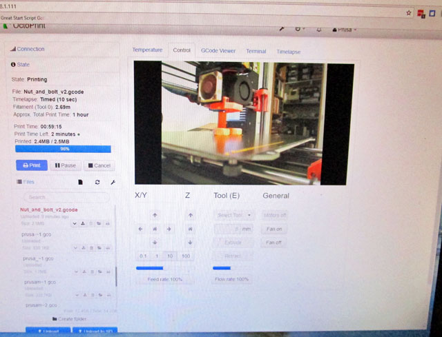
While the printer is printing, you can watch its progress on OctoPrint. This is especially handy if the printer
is located some distance from your computer. In my case, I expect my printer to eventually be located in
my shop. It is possible (but probably not practical) to operate it from anywhere in the world!
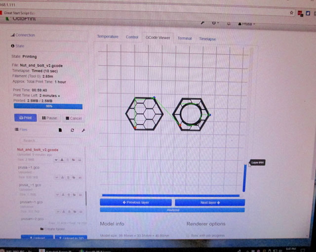
Another option during operation is to watch the actual path the extruder is taking real time. Here we see an
internal layer which typically is composed of an outline with the inner portion made of very low density
filler patterns. This saves both printing time and material.
I plan to eventually build an enclosure around my printer. Some materials require a warmer ambient temperature
and are very sensitive to drafts. Prusa published a modification to lessen the amount the bed cable hangs over the rear
meaning a smaller enclosure can be made. The cable entry block used to point the cable directly out the back. This
one for which they published the build file exits the cable along the rear, saving about 6 inches of overall depth.
I printed and installed it in preparation for the future. It also means I can now place the printer 6 inches closer to a rear wall.
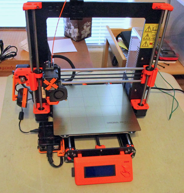
This is my printer as it stands at the time of this writing (4/3/18)
*The terms of use for Thingiverse require that credit be given to the designer when you display their designs.
.1. Thanks to luc_e who designed the Logitech C270 tripod Dec 27, 2015
(which I called the portable webcam)
2. Thanks to iDig3Dprinting who designed the XYZ 20mm Calibration Cube Jan 19, 2016
Using OctoPrint, you have the convenience of doing all the file handling on your desktop computer, but once it is sent to the printer (OctoPi) it is totally controlled by the Pi and the printer. No network, computer, or inadvertent operator errors can affect the print. There are also several cool features that only OctoPrint offers. During the printing, you have a choice of watching live video of the build, or a graphical representation of the path of the extruder as it builds the final object. During the setup stage you can communicate with the printer using a built-in terminal. Probably the best feature is the time lapse. You can specify how frequently it should take a snapshot which will become one frame in a video, how many frames a second the final video should show, and details about how to process it. This time lapse then can be run at any time, and is especially useful if there is a problem with the print. You should be able to review the video and hopefully see the cause of the problem. By opening a second copy of OctoPrint, you can display both the path of the extruder and the video at the same time. At this point, I plan to do most, if not all, my printing through OctoPrint!
While the printer is printing, you can watch its progress on OctoPrint. This is especially handy if the printer
is located some distance from your computer. In my case, I expect my printer to eventually be located in
my shop. It is possible (but probably not practical) to operate it from anywhere in the world!
Another option during operation is to watch the actual path the extruder is taking real time. Here we see an
internal layer which typically is composed of an outline with the inner portion made of very low density
filler patterns. This saves both printing time and material.
I plan to eventually build an enclosure around my printer. Some materials require a warmer ambient temperature
and are very sensitive to drafts. Prusa published a modification to lessen the amount the bed cable hangs over the rear
meaning a smaller enclosure can be made. The cable entry block used to point the cable directly out the back. This
one for which they published the build file exits the cable along the rear, saving about 6 inches of overall depth.
I printed and installed it in preparation for the future. It also means I can now place the printer 6 inches closer to a rear wall.
This is my printer as it stands at the time of this writing (4/3/18)
*The terms of use for Thingiverse require that credit be given to the designer when you display their designs.
2. Thanks to iDig3Dprinting who designed the XYZ 20mm Calibration Cube Jan 19, 2016
Yet more
mods! 6/3/18
I have been making parts and dreaming up further modifications for the printer. One of the features that Octoprint supports is remotely tuning the printer on and off. It turns out to be a fairly simple task (at least electrically and software wise). I purchased a solid state relay (SSR) which will easily handle much more current than my printer, and will reliably switch with the 3.3 volt logic level of the Raspberry Pi. I connected it, installed a plug-in to my Octoprint and it worked great! A new icon is shown in the Octoprint top bar. Clicking this icon will turn the printer on or off. OK, that was easy! Now where do I put the solid state relay and any other circuitry I decide to tie in to it?
I initially designed a mounting box that attached to the bottom of the power supply, mounting instead of the existing bottom cover plate. Initially it looked like a promising design, but then I started adding items I would like in the box other than the SSR, and things just did not fit.
I then looked at a box mounted on the top of the power supply where I had much more room and through a series of iterations I ended up with a box which solidly mounts on the power supply and is in series with the power cord to the printer. What this means is that I now plug the power cord from the wall into my new box, which contains the SSR and two convenience outlets, one powered on all the time and one that switches on and off with the printer. There is also a switch which will cut the power to the SSR regardless of the commands sent by Octoprint. There is a short cord from this box which plugs into the normal power connector of the printer. There is also a small data cable which connects to the Raspberry Pi to control the SSR. The un-switched outlet is for the 5 volt wall transformer which powers the Raspberry Pi. It stays on all the time so as to be available for turning on the printer. It is much more convenient this way, as you must do an orderly shut-down of the Pi before turning it off or risk corrupting the SD card contents. It would be all too easy to just kill the power and forget the shut down routine if it were controlled by the printer power switch. The Pi only draws about 2 watts, so it is not a problem to just let it run. I included a switched outlet for any accessory which I would like to be powered on and off as the printer is. The added switch is probably a little overkill, as the only thing it does that the normal printer power switch doesn't is to remove all power from the SSR and the switched outlet ( but not the always-on outlet).
I have been making parts and dreaming up further modifications for the printer. One of the features that Octoprint supports is remotely tuning the printer on and off. It turns out to be a fairly simple task (at least electrically and software wise). I purchased a solid state relay (SSR) which will easily handle much more current than my printer, and will reliably switch with the 3.3 volt logic level of the Raspberry Pi. I connected it, installed a plug-in to my Octoprint and it worked great! A new icon is shown in the Octoprint top bar. Clicking this icon will turn the printer on or off. OK, that was easy! Now where do I put the solid state relay and any other circuitry I decide to tie in to it?
I initially designed a mounting box that attached to the bottom of the power supply, mounting instead of the existing bottom cover plate. Initially it looked like a promising design, but then I started adding items I would like in the box other than the SSR, and things just did not fit.
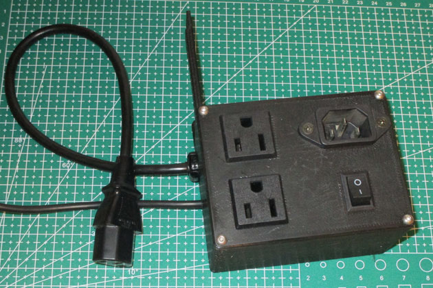
I then looked at a box mounted on the top of the power supply where I had much more room and through a series of iterations I ended up with a box which solidly mounts on the power supply and is in series with the power cord to the printer. What this means is that I now plug the power cord from the wall into my new box, which contains the SSR and two convenience outlets, one powered on all the time and one that switches on and off with the printer. There is also a switch which will cut the power to the SSR regardless of the commands sent by Octoprint. There is a short cord from this box which plugs into the normal power connector of the printer. There is also a small data cable which connects to the Raspberry Pi to control the SSR. The un-switched outlet is for the 5 volt wall transformer which powers the Raspberry Pi. It stays on all the time so as to be available for turning on the printer. It is much more convenient this way, as you must do an orderly shut-down of the Pi before turning it off or risk corrupting the SD card contents. It would be all too easy to just kill the power and forget the shut down routine if it were controlled by the printer power switch. The Pi only draws about 2 watts, so it is not a problem to just let it run. I included a switched outlet for any accessory which I would like to be powered on and off as the printer is. The added switch is probably a little overkill, as the only thing it does that the normal printer power switch doesn't is to remove all power from the SSR and the switched outlet ( but not the always-on outlet).
The completed box has a switch, two outlets, and a power input connector. The power cable on the left plugs
into the normal power cord connector on the printer. The small cable brings the signals from the Raspberry Pi.
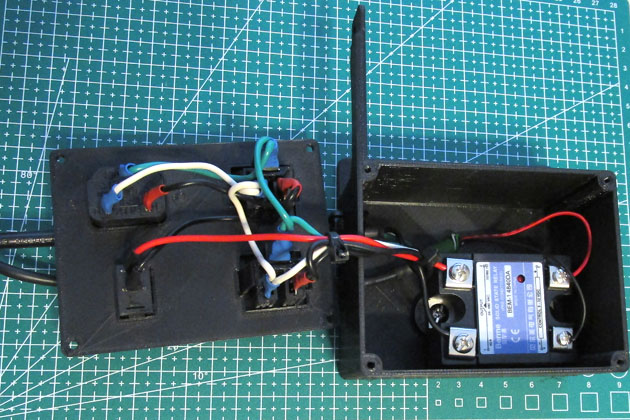
The only component inside the case is the solid state relay.
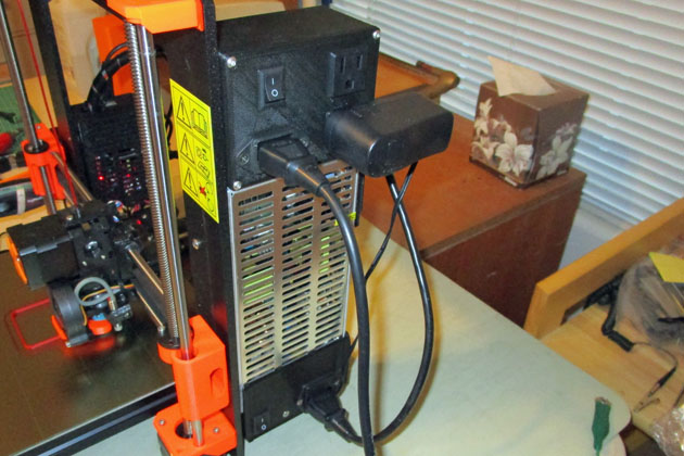
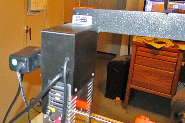
Fully installed, the box looks like it is an original part of the printer.
The box mounts to two threaded inserts in the power supply on the side (as looking at the front of the printer) and one
on the back which anchors a long stabilizing arm. The three screws hold the box very securely.
I also did some re-modification.
I discovered a couple
problems with the 90 degree cable exit from the heated build
plate. The cable is pulled tighter than I like when the table is
all
the way forward, and the angle of the loop this cable makes in some
positions interferes with the cable loop from the extruder at certain
positions of it. The cables push against each other, then lightly
snap past each other.
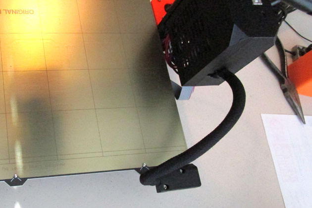
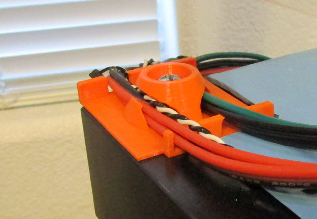
Prusa showed a 60 degree exit block which looked to solve at least the cable pulling problem, so I printed and installed it. The cable could still hit the other cable, so I cut a cable tie which held the cable pointing up as it left the control box. I then designed and printed a cable guide which fastened in its place. The cable now exits the control box pretty much level and can no longer hit the other cable. In addition, the cable is not under the strain of being pulled tight in certain table positions.
Prusa showed a 60 degree exit block which looked to solve at least the cable pulling problem, so I printed and installed it. The cable could still hit the other cable, so I cut a cable tie which held the cable pointing up as it left the control box. I then designed and printed a cable guide which fastened in its place. The cable now exits the control box pretty much level and can no longer hit the other cable. In addition, the cable is not under the strain of being pulled tight in certain table positions.
The 90 degree cable block on the left causes the cable to be pulled at a sharper angle than I like. The 60 degree exit block on the right solves that problem and still prevents
the cable loop from extending as far to the back allowing a smaller enclosure than the original setup. The strain relief on the control box keeps the cable secure and level.
I made what I call my "gooseneck camera" by printing several extra forks from the adjustable webcam mount
shown above. I mounted a camera designed as an accessory backup camera for a car (except this one is for the
front of the car) on the top and connected it to a spare channel of my security system. I can now keep tabs
on my prints in other parts of the house or even on my cell phone when I am away from home if I desire.
Added an
Enclosure 6/1/18
I have now started to build my planned-for enclosure. An enclosure has several advantages for a 3D printer:
Searching the Internet, I found many, many Lack table designs. Recently Prusa added their own design to the mix and I really liked the result. They suggest using either two or three stacked tables, with the lower ones providing a work platform for the printer and the top one being the actual enclosure. They provided a number of 3D printed part files and good instructions on how to proceed.
I purchased 3 Ikea Lack tables for $7.95 each (plus $9 to ship them all) and then started printing out parts. Prusa grouped their parts so you print all 4 sets of the upper support parts together, all 4 of the lower support parts together, and several individual parts. While I was waiting for some "Prusa orange" filament to arrive (I wanted to use the higher temperature rated PETG filament, although I'm sure that PLA would have been fine) I printed several other parts, including a new reel holder, as the existing one will not fit inside. Other parts provided for mounting the heat sensitive power supply outside the enclosure. Apparently the main control board and the display will withstand the somewhat higher temperatures. I designed and printed a set of stepped angles to keep the two bottom tables aligned.
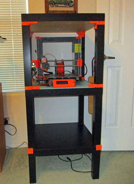
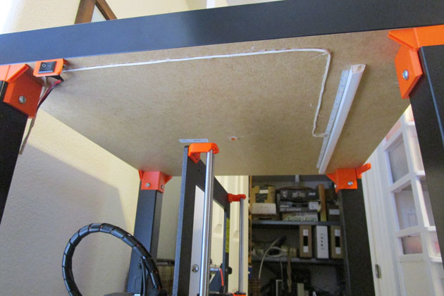
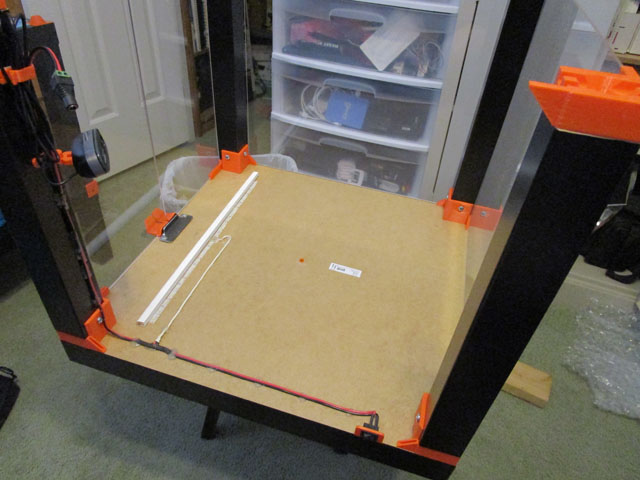
This is the enclosure after the initial assembly. Each end of the top table's legs has a printed part which will hold the plexiglas windows
and doors, and keep the top two tables aligned. I printed some angles fastened to the bottom table which keep the #2 table legs properly
positioned. Since the letgs are set in slightly from the table top, the angles are thin on the bottom and thick on the top. The legs of the bottom
table have been shortened to place the printer at a good work height.
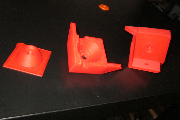
The main parts Prusa provided print files for, are the support blocks. The left cone device fastens to the corners of the
#2 table top. The center part is fastened to bottom of the legs of #3 table and is located by the cone when the
tables are assembled. The wings sticking out are slotted to support the corners of the 3mm (1/8 in.) plexiglas. The right
hand block fastens the legs of #3 table to the top and also has the plexiglas holding wings. The blocks for the front
have a hinging part for the plexiglas to provide split doors for access. They also provided door handles which
double as magnetic latches.
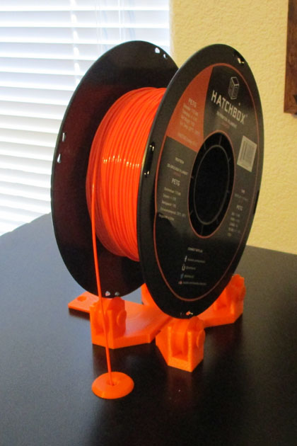
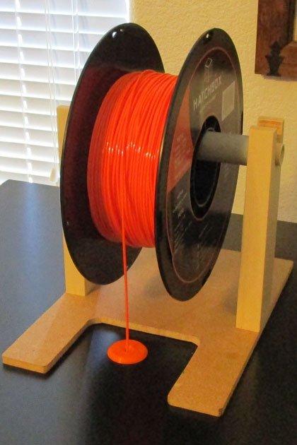
With the enclosure I needed a new reel holder, so I printed the one from Thingaverse that Prusa recommended (left). I don't like it at all! It constantly
makes creaking and snapping sounds as I print, but worst of all, even after cleaning and smoothing the bearing surfaces, the reel would rather
slide on the rollers than have them roll like it was designed.
On the right is my answer. I temporarily abandoned the 3D printer and went back to my old shop techniques and came up with an easy to load,
quiet, low friction holder. Yes I could have printed it, but it would have taken a lot of plastic and time to print, and just because I have the printer
doesn't mean it is always the best solution for the job.
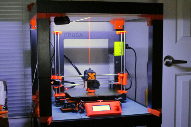
I wanted to light the enclosure. Prusa suggests mounting a strip of LEDs on the top. I thought it might be better on the inside edge of the two front legs. I ran
a simple test, and the overhead ones won. I had a reel of LED's with an adhesive backing. Since the Prusa power supply is 24 volts, and my LEDs are 12 v.,
I connected two strips in series and stuck them to the top. As I had previously had some of these LEDs fall off when the the adhesive got warm, I also stapled the
strip up in a number of places. I stuck the wiring in place with hot glue, printed out a switch mount and wired the switch into the circuit. Since my sitting height in the
office is below the LED's, they caused a glare so I added a quarter round strip to block the light to the front. The LEDs light whenever the printer is on,
unless I turn them off with the added switch.
The second picture shows the illuminated enclosure at night. It is easily bright enough for my casual viewing, and the web cam gives a clear, bright picture.
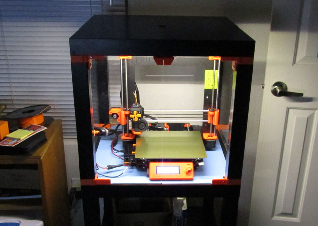
I have removed the original LED strips and replaced them with the new. I also totally rewired it. The wire
now comes down a front leg instead of the rear one. It was very hard to reach through and plug and unplug
it before.
The illumination is now excellent!
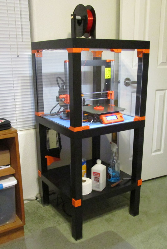
And here is the finished enclosure!
I have now started to build my planned-for enclosure. An enclosure has several advantages for a 3D printer:
- It will keep it cleaner. The precision guide rods and lead-screws have a thin coating of lubricant, and will easily collect dust and contaminants.
- There are plastics which require a warmer, draft free environment to print well. ABS is the most popular plastic with these limitations.
- Certain plastics give off an odor as they print (i.e. ABS). A non-ventilated enclosure helps, but does not totally solve this problem.
- An enclosure will muffle any noises made by the printer making the operation quieter.
Searching the Internet, I found many, many Lack table designs. Recently Prusa added their own design to the mix and I really liked the result. They suggest using either two or three stacked tables, with the lower ones providing a work platform for the printer and the top one being the actual enclosure. They provided a number of 3D printed part files and good instructions on how to proceed.
I purchased 3 Ikea Lack tables for $7.95 each (plus $9 to ship them all) and then started printing out parts. Prusa grouped their parts so you print all 4 sets of the upper support parts together, all 4 of the lower support parts together, and several individual parts. While I was waiting for some "Prusa orange" filament to arrive (I wanted to use the higher temperature rated PETG filament, although I'm sure that PLA would have been fine) I printed several other parts, including a new reel holder, as the existing one will not fit inside. Other parts provided for mounting the heat sensitive power supply outside the enclosure. Apparently the main control board and the display will withstand the somewhat higher temperatures. I designed and printed a set of stepped angles to keep the two bottom tables aligned.
This is the enclosure after the initial assembly. Each end of the top table's legs has a printed part which will hold the plexiglas windows
and doors, and keep the top two tables aligned. I printed some angles fastened to the bottom table which keep the #2 table legs properly
positioned. Since the letgs are set in slightly from the table top, the angles are thin on the bottom and thick on the top. The legs of the bottom
table have been shortened to place the printer at a good work height.
The main parts Prusa provided print files for, are the support blocks. The left cone device fastens to the corners of the
#2 table top. The center part is fastened to bottom of the legs of #3 table and is located by the cone when the
tables are assembled. The wings sticking out are slotted to support the corners of the 3mm (1/8 in.) plexiglas. The right
hand block fastens the legs of #3 table to the top and also has the plexiglas holding wings. The blocks for the front
have a hinging part for the plexiglas to provide split doors for access. They also provided door handles which
double as magnetic latches.
With the enclosure I needed a new reel holder, so I printed the one from Thingaverse that Prusa recommended (left). I don't like it at all! It constantly
makes creaking and snapping sounds as I print, but worst of all, even after cleaning and smoothing the bearing surfaces, the reel would rather
slide on the rollers than have them roll like it was designed.
On the right is my answer. I temporarily abandoned the 3D printer and went back to my old shop techniques and came up with an easy to load,
quiet, low friction holder. Yes I could have printed it, but it would have taken a lot of plastic and time to print, and just because I have the printer
doesn't mean it is always the best solution for the job.
I wanted to light the enclosure. Prusa suggests mounting a strip of LEDs on the top. I thought it might be better on the inside edge of the two front legs. I ran
a simple test, and the overhead ones won. I had a reel of LED's with an adhesive backing. Since the Prusa power supply is 24 volts, and my LEDs are 12 v.,
I connected two strips in series and stuck them to the top. As I had previously had some of these LEDs fall off when the the adhesive got warm, I also stapled the
strip up in a number of places. I stuck the wiring in place with hot glue, printed out a switch mount and wired the switch into the circuit. Since my sitting height in the
office is below the LED's, they caused a glare so I added a quarter round strip to block the light to the front. The LEDs light whenever the printer is on,
unless I turn them off with the added switch.
The second picture shows the illuminated enclosure at night. It is easily bright enough for my casual viewing, and the web cam gives a clear, bright picture.
Moving the
power supply
Since the power supply was not designed to be run in particularly hot locations, Prusa suggests moving it to outside the enclosure, and includes files to print to facilitate this. If you are really careful and don't mind stretching your cables, the original cabling from the power supply to the control box would just reach with the supply relocated. I replaced the two power cables with longer ones, and spliced an extension into a signal cable which detects power failures. This gave me plenty of length to route the wiring the way I wanted and makes the overall installation neater. With the addition of the Octoprint, I also had a power cable to the Raspberry Pi, and the data cable between the Pi and the solid state relay. Prusa provided for the normal cables to pass from outside to inside the enclosure by adding an opening which went through one side of a lower mounting block and the alignment cone under it. With the added Octoprint wires and a ground wire I added, there was no way they would fit in the supplied opening! Even though Prusa supplied the source files for these parts, they were not supported by any of the CAD programs I have learned. Out with the calipers and into Fusion 360 to redesign these parts. It was really not difficult to recreate the parts as Prusa had designed them, then add a second wiring path on the other side. Now I had enough room for all my wires.
When it came to mounting the power supply it was the same story. Since adding the extra electrical box to the top of the power supply (bottom when mounted on the enclosure frame), it was now too large for the Prusa designed holder. I also redrew it with slightly different dimensions and it all fit in just fine.
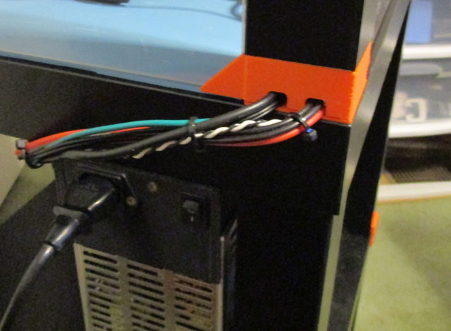
The new part with double wire openings works with my wires just fine. I initially had a problem with the wires bending after leaving the cone slots making it hard
to fit the leg block over them, so I added wire guides to the cone on both sides. The right shows the wires going through the assembled enclosure (prior to the guides).
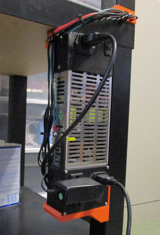
The power supply slips into a holder under table #2. There is a guide clip at the top which doesn't show here. If I should
want to take just the printer somewhere to run, I can remove the top of the enclosure, unplugging 2 cables, slip the power supply
out of its holders and swing it up to its original position on the printer. In about 3 minutes I can remove a replacement support
and install the power supply. The cable will now run around the rear of the frame instead of being thoroughly intermeshed
through the center.
Since the power supply was not designed to be run in particularly hot locations, Prusa suggests moving it to outside the enclosure, and includes files to print to facilitate this. If you are really careful and don't mind stretching your cables, the original cabling from the power supply to the control box would just reach with the supply relocated. I replaced the two power cables with longer ones, and spliced an extension into a signal cable which detects power failures. This gave me plenty of length to route the wiring the way I wanted and makes the overall installation neater. With the addition of the Octoprint, I also had a power cable to the Raspberry Pi, and the data cable between the Pi and the solid state relay. Prusa provided for the normal cables to pass from outside to inside the enclosure by adding an opening which went through one side of a lower mounting block and the alignment cone under it. With the added Octoprint wires and a ground wire I added, there was no way they would fit in the supplied opening! Even though Prusa supplied the source files for these parts, they were not supported by any of the CAD programs I have learned. Out with the calipers and into Fusion 360 to redesign these parts. It was really not difficult to recreate the parts as Prusa had designed them, then add a second wiring path on the other side. Now I had enough room for all my wires.
When it came to mounting the power supply it was the same story. Since adding the extra electrical box to the top of the power supply (bottom when mounted on the enclosure frame), it was now too large for the Prusa designed holder. I also redrew it with slightly different dimensions and it all fit in just fine.
The new part with double wire openings works with my wires just fine. I initially had a problem with the wires bending after leaving the cone slots making it hard
to fit the leg block over them, so I added wire guides to the cone on both sides. The right shows the wires going through the assembled enclosure (prior to the guides).
The power supply slips into a holder under table #2. There is a guide clip at the top which doesn't show here. If I should
want to take just the printer somewhere to run, I can remove the top of the enclosure, unplugging 2 cables, slip the power supply
out of its holders and swing it up to its original position on the printer. In about 3 minutes I can remove a replacement support
and install the power supply. The cable will now run around the rear of the frame instead of being thoroughly intermeshed
through the center.
The original LEDs I installed
didn't
work out too well. After just a few days of operation I noticed 3
of the bulbs were quite dim. The following day there were
4. All had looked equal originally. Amazon had a reel of
"warm white" higher power LEDs for about $10 so I ordered them and
installed a pair of series wired strips like the original. I
found an on-line hint that hot glue would remove quite easily if you
wet around the edges with rubbing alcohol. I tried it and it
really works! I had no problem easily lifting each of the glue
"globs" where I had attached wiring or the lights themselves. I
again used hot glue on the new wiring and LED strips. The light
is now much brighter and does not have the blue tint of the old
LEDs. So far the lights all look equal and bright!
I have removed the original LED strips and replaced them with the new. I also totally rewired it. The wire
now comes down a front leg instead of the rear one. It was very hard to reach through and plug and unplug
it before.
The illumination is now excellent!
And here is the finished enclosure!
I am now printing more items for
other
things than I am for the printer itself. That's a
milestone. I am using Octoprint exclusively and I love it.
I think I now have a working, always ready to use machine, and a fairly
efficient work flow to design and build good parts quickly and
inexpensively!
GO BACK TO "3D Print, House, & Misc. Projects"
R. S. Mason April 2018