When I sold my motor home 2 1/2 years ago, I offered to sell the buyer my Suzuki XL-7 tow car for a nominal package price and he turned me down. Recently, I received a call from him asking if I still had the car, and if I would be willing to sell it to him. After some negotiating, we agreed on a price (that was higher than originally offered) and I sold him the car. I had delayed selling the car as it was a true 4 wheel drive, and I have decided that living in sometimes snowy Prescott, I wanted to keep a 4 wheel drive vehicle. What I really wanted, now that I no longer need a towable car, was a pickup truck, and I started keeping my eyes open for a decent one I could afford.
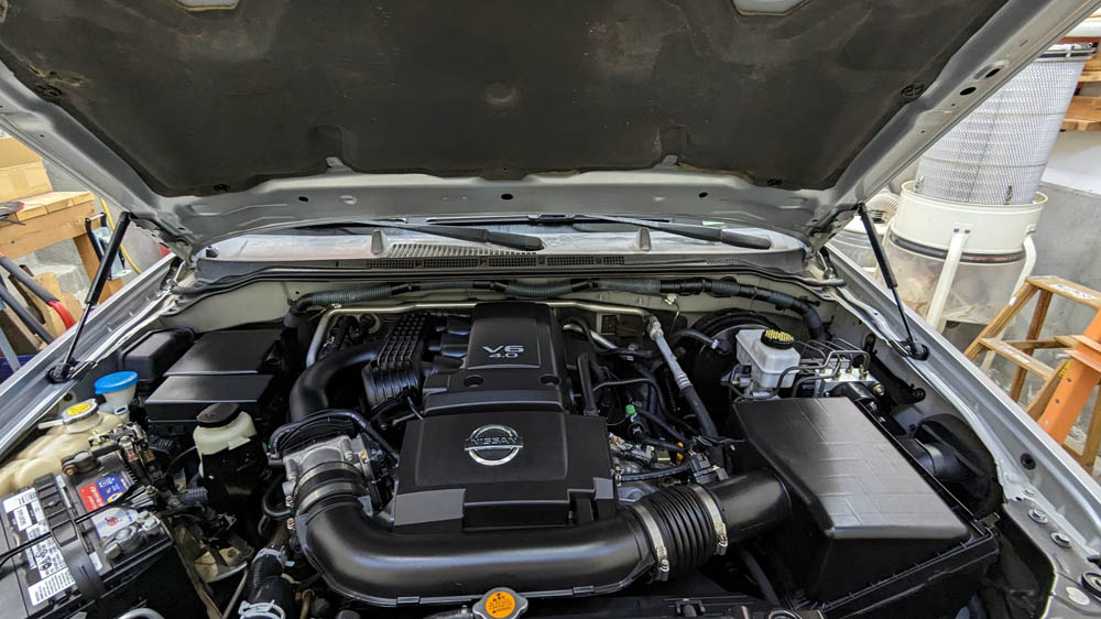
After some online searching, I found a nice Nissan Frontier pickup with a rear shell at our local Honda dealer. His offered price was somewhat higher than some I had seen online, but in other areas. It ticked all the boxes of what I wanted, and as it turned out, their price was right in line after some serious negotiating. (I hate that!) The truck was in very good condition for its age, and I really could not afford one much newer for a secondary vehicle which will not be driven that much. It has a 4 liter V6 dual overhead cam engine, an automatic transmission, and 4 wheel drive. The tires are brand new . It is classified as a Crew Cab and has rear seats, but not much knee room. It also has a 6 foot long bed.
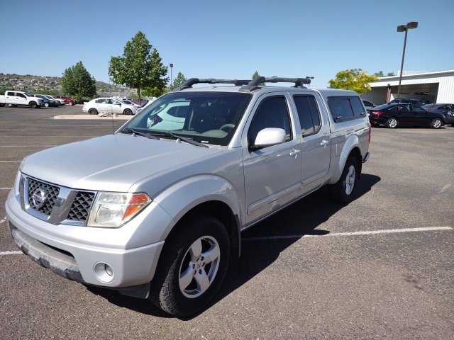
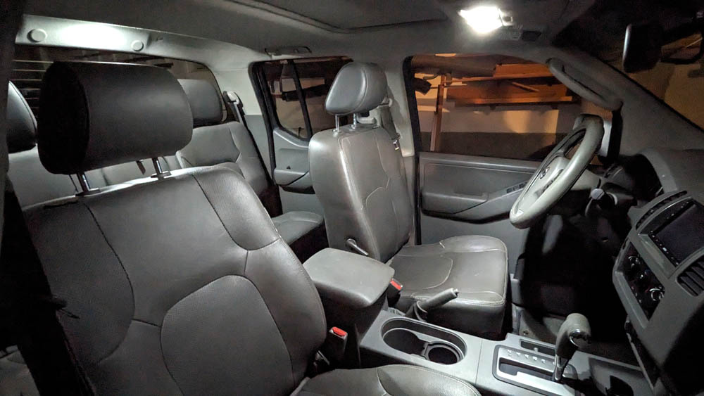
The 4 wheel drive truck is in quite good condition. The LE trim model is the one which has all the "goodies", such as power leather, heated seats, a powered sun (moon?) roof,
premium sound system, roof rack, super tie down system in the bed, etc. It also came with a shell over the bed. A bottle of touch-up paint will help cure the "road rash" in
several places.
Updated radio:
With the shell on, the rear visibility from the cab is not very good, so the first order of business was to replace the radio with one containing a 7 inch screen and add a backup camera. I have made this modification on my Jeep, the Tracker, the Suzuki, and now the Frontier! My Volt came with a backup camera system, but I changed the camera to get better resolution. Yeah! I really like backup cameras!
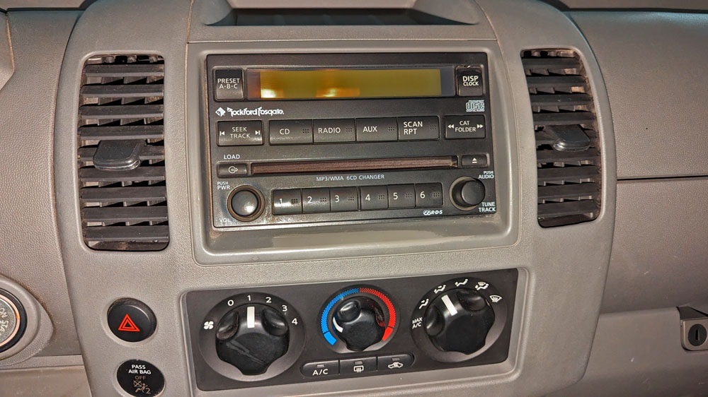
The original radio was a high-end unit for its day, but by today's standards is very dated. The great thing
about it is it is a double DIN size, the size most replacement radios today fit.
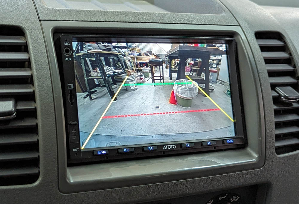
The radio I chose is an Atoto F7 which has several interesting features. It supports a backup camera, a front camera, and a spare video input. The cameras (only the backup in my case) can be turned on independently of having the car in reverse, so you can monitor traffic behind you as you drive. When you put the transmission in reverse, the camera comes on, if not already on, and backup guide lines are added. These backup lines have a feature I have dreamed about on previous cars, but have not been able to realize until now. The lines are fully adjustable in the setup menu. I have mine set so the yellow side lines fairly accurately define the width of the truck as it backs up. The green safety cross line is 6 feet behind my bumper, and the red line is 2 feet.
Other relevant features of this radio, besides a slew of music input options are that it supports both Android Auto and Apple Car Play. These allow full interaction of an app on your phone on the 7 inch screen. This is ideal for using your phone for navigation using the car's built in larger screen.
Installation was fairly typical with the need to make a harness by combining the pigtail harness that came with the radio with a similar harness purchased to mate with the truck's original radio connectors. I was able to use the original mounting brackets by slightly slotting 2 of the mounting holes on each side. After completing the electrical and the mechanical installation it was time to test it. I turned it on, it lit up and showed it was receiving a station, but THERE WAS NO SOUND!
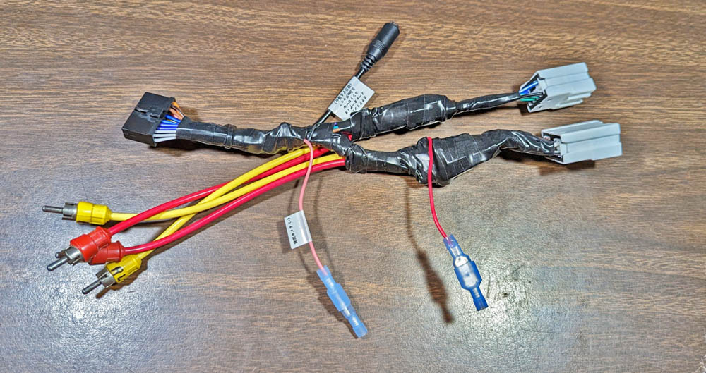
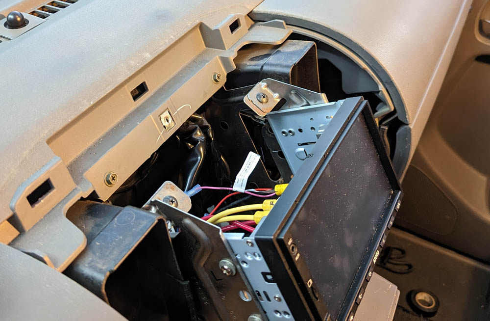
When I discovered that I truly had the premium radio, I had to modify my harness to include cables to plug into the various pre-amp outputs. The plugs
to connect to the new radio are on the left, while the two white connectors on the right plug into the truck wiring harness. The side wires are to the backup
lights to indicate the truck is in reverse, the power cable to the camera, and the connector for the steering wheel controls.
The right picture shows that with the panels removed, there is wonderful access to the rear of this radio. Fortunately is is very thin, while the original
radio extended 6 1/2 inches back into the dash.
Before starting the installation, I had to determine if the truck contained a "normal" radio or if it had the Premium Sound System. One of the larger after-market suppliers of automotive electronics showed for my truck a trademark label on the driver's door if it contained the premium system. My door had no such label, therefore I must have the normal system, right? WRONG! It turned out that I do have the premium system, which includes an added amplifier under the front passenger seat. Sending the amplified audio from the radio to this amplifier would result in extremely loud, distorted sound - if the amplifier were powered up. However, I did not connect the "amp enable" wires when I made the harness, as I thought I had no amp. I also discovered that the "thing" under the rear left seat is a sub-woofer, and that I have tweeters on the dash and in the rear doors to supplement the normal door speakers.
I rewired my harness to include wires for 4 pre-amplifier outputs using RCA jacks on the radio in place of the speaker outputs, I also connected the "amp enable" wire. Now it all worked just fine. I also connected the steering wheel control wires and have 6 user definable inputs to the radio using the buttons on my steering wheel. I chose volume up and down, rear camera on and off, and answer and hang up the hands-free phone function.
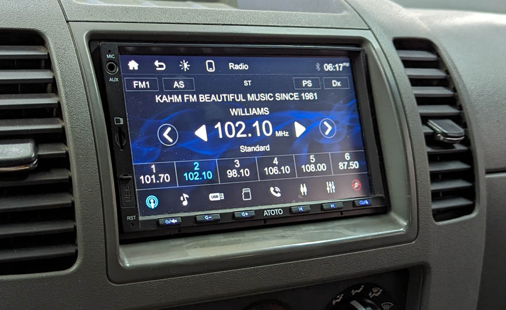
The left shows the normal screen I like while driving with a music station playing. There are specialized screens for
every function, and the touch screen makes it easy to switch.
The right shows the backup image (in my RV garage workshop) and the adjustable guide lines. The lines do not show if you
select the camera while driving.
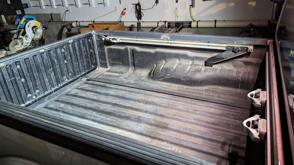
Cap removal and storage system:
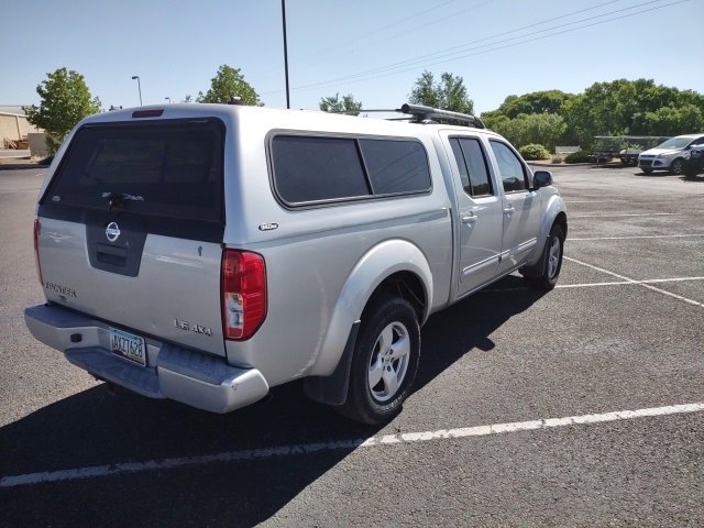
The cap (also called a shell) on the rear of the truck is very nice and certainly will protect any contents in the truck bed, but it also limits the usefulness of the truck. I need a way to remove and re-install the cap by myself, and I also need to find a place and method of storing it when it is off the truck.
I discovered a device designed to lift items from car roofs such as kayacks, Jeep removable tops, and pickup truck shells, and store them by hanging them from the ceiling! It looked like a good solution, but was over $200, and I figured I could do something similar, but for less money. I did the rough design of several systems and did some approximate pricing and discovered that I could not save very much money by doing quite a lot of work! I ended up ordering the Hoister system from Harken Inc. They make several models for different weight ranges of loads. I chose the largest size with a weight limit of 200 pounds. This consists of a system of marine lines (ropes to us common folks), high quality pulleys, and a patented anti-drop mechanism which grabs the line as you release tension on it so the load will stay at its height, without dropping at all as you release each pull. To lower the load, you pull the line at an angle to the wall and the mechanism releases its grip.
Most of these systems are installed in the normal garage, however since my garage has a very low 8 foot high ceiling, this was not an option. Instead I decided to install it in my RV garage, now a woodworking shop, on its 16 foot high ceiling.
I am very impressed with the overall quality of the kit. The pulleys are stainless steel side plates with a plastic pulley inside. If you spin the pulley, it will continue spinning for about 10 seconds before stopping! It turns out that Harken's primary business is producing rigging for yachts. They claim their equipment is on all the championship yacht racers. The quality shows.
The system has 4 drop lines coming from pulleys on a pair of 6 foot 4 inch 2x6's (I supplied them) bolted through the ceiling into the trusses. The bottoms of these lines are connected to a pair of flat 7 foot long straps which have a quick disconnect latch. The 4 lines are connected to an 8 to 1 ratio block and tackle which runs between the 2x6's and the wall. The pull line drops from the ceiling at the wall and allows you to raise or lower the 4 drop lines. With my system I can raise the cap to about 8 feet from the floor for storage, down to about 30 inches for placing the cap on saw horses if that should ever be desired.
Harken offers this system for either 10 or 12 foot maximum ceiling height, but not for a 16 foot height as I have in the RV garage. To accommodate, I had to extend each of the 4 drop lines. I researched strong knots on-line and decided on using the Flemish bend (also called the double figure 8 knot). This knot is proported to be stronger than the rope, certainly stronger than the less than 50 pound load on each line.
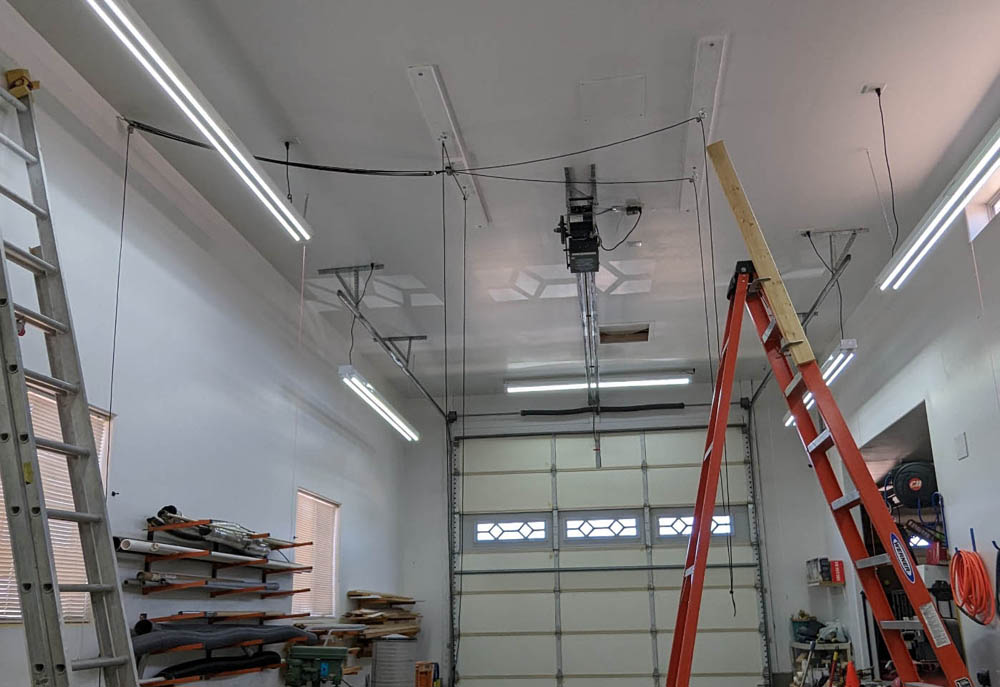
This shows the system after the basic installation is complete. I have yet to extend the down lines and attach the straps. I painted the two
6 foot 4 inch 2x6's and attached all the hardware in advance. The most difficult part of the whole job was then lifting them to the ceiling, positioning
them correctly, and getting the first lag bolt in and tightened. The rest was relatively easy, except for constantly climbing down, moving the
ladder, then climbing back up. Oh, if only I had a scaffold, a bucket truck, or a scissor lift!
The 2x4 clamped at the top of the ladder was to provide me solid support when I was working from a couple steps from the top. It was
wonderful (necessary) to have a good hand hold when up there.
I also had to raise one fluorescent (now LED) light fixture. If it stayed at the lower level of the others, I could not pull the line at a sufficient
angle to release the line.lock
To solve the problem of the lines hanging down into the center of the
RV garage when the cap is on the truck, I mounted a single pulley near
the ceiling and ran a light nylon line with a caribiner
on the end. I clip this to all 4 of the lines, lay the straps
over the top and pull it all to the edge of the ceiling. A 3D
printed cleat on the wall holds it all in place.
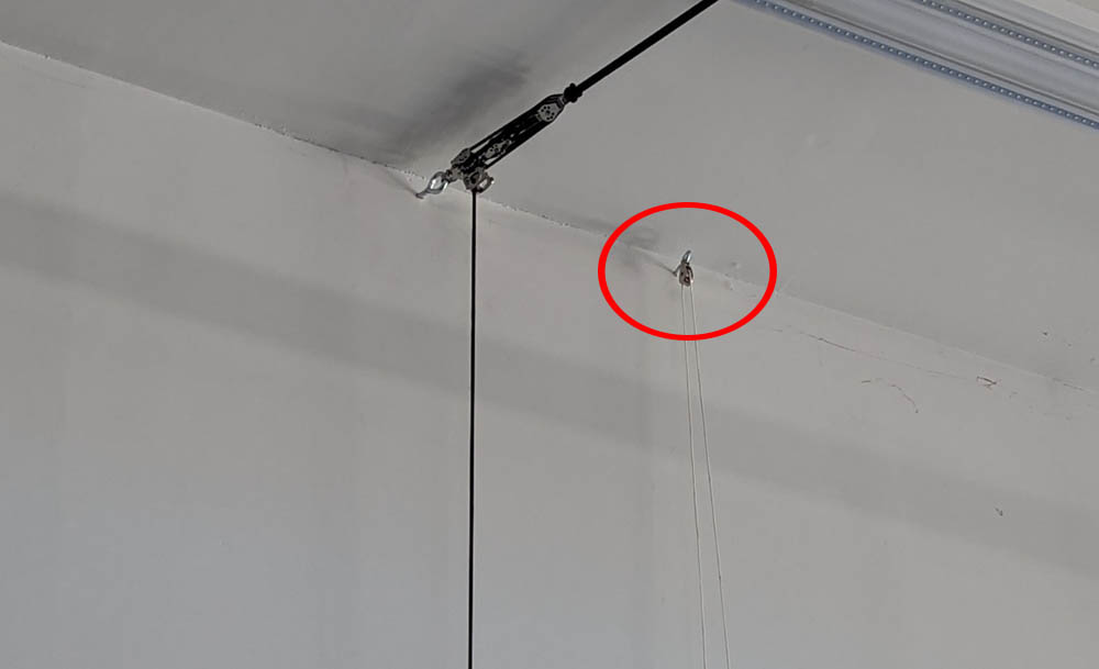
No, this is not a circus trapeze setup! It is my way of handling the lines when they are not in use. I fastened a small pulley to the right of the main lifting lines and ran a light
nylon cord which I can attach to the 4 down lines. Pulling them up to the ceiling creates an interesting pattern, but most importantly gets them out of the way.
One anticipated problem of running the straps around the cap is that I have to lift the cap slightly above the edge of the truck bed so I can pass the straps through. As the cap has a channel around the bottom which straddles the bed wall and overlaps it by about 2 inches, I have to lift the cap these 2 inches plus enough to actually fit the strap under it. I made a set of 3/4 inch thick blocks to place under the cap once it is lifted. Of course the reverse is true upon replacing the cap. I have to set the cap on the blocks, remove the straps, then remove the blocks and lower the cap to the truck, again, almost 3 inches total at each corner.
The first time I removed the cap, I lifted each corner by lying on my back in the bed and using my feet to lift the corner of the cap. I could then slip in the block and release the cap. This is NOT the way to do it. I initially made a very simple tool consisting of a vertical board and a horizontal one, pivoting on a bolt giving me about a 4 to 1 lever ratio. I could stand this up under the corner, put the edge of the horizontal board under the inside of the channel and lift it. It worked OK, but I don't like lifting by the edge of the sheet metal forming the channel. I then re-made the tool giving me a small pin on the end of some MDF. There are 3 locations along each edge of the cap where the channel widens for the hold down clips. In these areas I can get the pin up into the channel and lift on the flat top surface. This is far better. Of course my "quick trial" MDF pin did not last long (it did 2 corners OK, and broke on the 3rd), but it proved the concept. Making the pin of steel will give me a practical working tool.
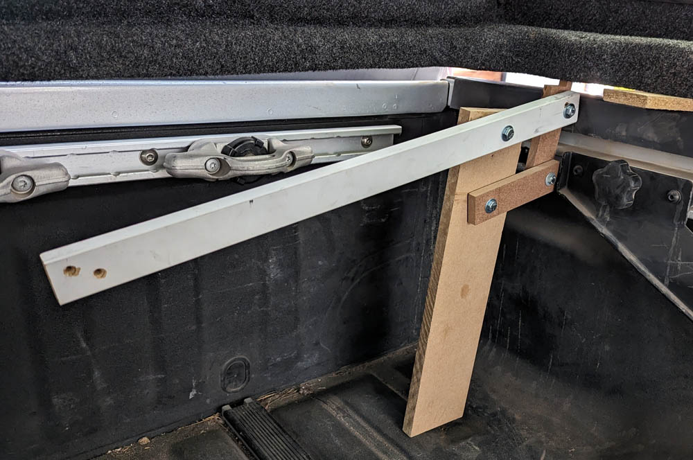
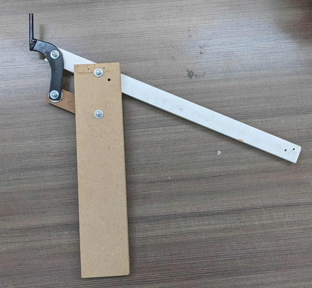
The left picture shows my makeshift tool after lifting the corner and inserting the spacer block. Taking what I learned I replaced the outer MDF block with a piece of scrap steel,
already in a curved shape to which I welded a 3/8 steel rod. This not only should be durable, but the extension of the pin sideways should allow better clearance around obstructions.
I'll have to wait until I put the cap back on the truck to try it out.
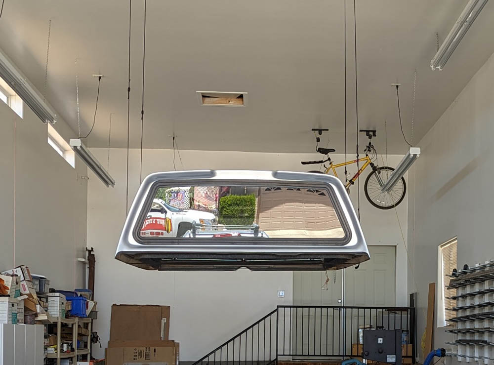
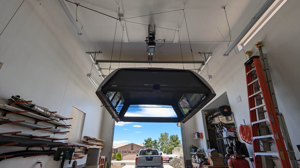
I included these two photos just because I found them interesting. The left shows what a great mirror the front shell window makes, vividly showing a somewhat magnified view
of across the street. The right picture just caught my interest with the bright blue sky and white clouds and showing a direct view of across the street.
The other problem, which I did not anticipate, was during lowering the cap back onto the truck. As the cap contacted the blocks on the bed walls, the load on the locking mechanism reduced enough that it locked the line, and I could not lower the cap all the way. Even after I adjusted all the lines so that the contact was pretty well even, the line locked before I could finish releasing all the tension. My initial solution was to hook a short rope to one of the down lines, and through a loop near the floor, press down with my foot. When applying a considerable part of my body weight, I estimate about 100 pounds, the lock released and I could pull the needed slack. This is NOT the answer, as putting that much of my weight on a totally unstable, hanging rope makes it hard to keep my balance.
My solution to this problem was to design and build a small addition to the line locking mechanism which allows me to pull yet another light line which will cause the locking pawl to be pulled away from the rope, thus disabling the locking function. Now, after lowering the cap to the first contact with the truck, I can pull this additional string and easily set the cap completely down plus I can pull one of the down lines for a little extra slack. It works like a charm.
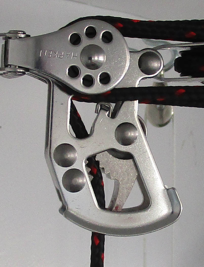
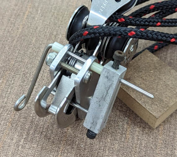
The left shows the line locking mechanism which is a part of the fixed end of the block and tackle. The locking pawl is seen in the lower hole, and pressing it to the right will
release it. The right picture shows my solution. Two aluminum plates are clamped to the locking mechanism and securely positioned by snug fitting holes around the rivet heads.
The stainless steel rod with the loop can be pulled by the nylon line, which rotates the bar on the right with a pin passing behind the pawl. The rotation pulls the pawl away from
the lifting line. And yes, I did cut off the excess length of the top rod after taking this picture. I made a slight flat surface on the main rod so the block will not slip.
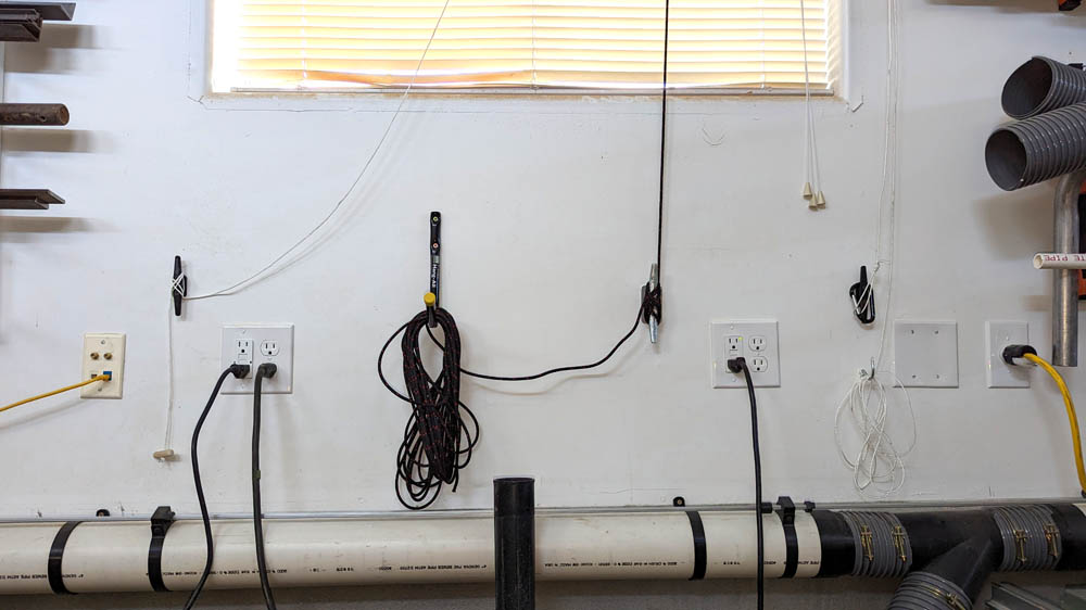
The Hoister has pretty well consumed one of the few available wall spaces remaining! In the center is the main pull
line, a safety cleat securing it, and the storage hook for the excess line. To the right is the light line which will pull
all the empty lines up high, out of the way, and below it, a small hook for storing it's excess line. The left light
line is the lock release. I could have made these a lot more compact as the safety cleat is the only one really
needing to be mounted to a stud, but I had the room and used stud mounting for everything.
In practice, this release works very well. After lowering the cap down to contact the blocks on the truck rails, I then pull the release line and lower just a little more to release the stored up tension. It only takes a short, light pull to activate the release. Then for good measure I grab one of the down lines and give it about an inch or so extra to provide just enough slack to easily release the latches on the straps, and provide enough slack to hook it all up next time. It is a big improvement!
Miscellaneous ModsLED lights:
I replaced the interior dome and map light bulbs and their dull orange glow with LED bulbs which give off a bright daylight colored illumination. I also replaced the high stop light and cargo light on the back of the truck cab with LED bulbs. The old bulbs were a dark gray in color and could not have been transmitting very much of their light through the bulb's discolored glass.
The LED's brightness and daylight color do an excellent job of illuminating the interior. I can now read by their light, a task I would have struggled with using the old bulbs. On the right,
the cargo lights really light up the bed in a dark garage. Unfortunately, when the cap is on, these lights shine into a solid panel of fiberglass several inches away. I have not yet investigated
the lighting options in the shell, but I do know that the brake light.is duplicated above the rear window of the shell.
Hood prop bar removed:
For under $30, I bought a kit containing 2 gas cylinders and several brackets which will hold the hood open without using a prop bar. The installation took less than 30 minutes and now the hood is much lighter and easier to lift the first foot or so. From that point the cylinders are trying to lift the hood and you need to hold it back. The hood also opens about a foot higher than it did with the prop bar.
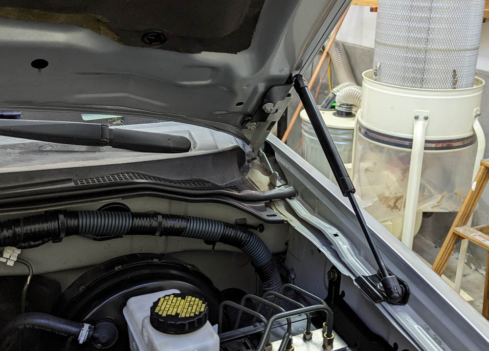
The two gas struts do a fine job of holding the hood open. As shown on the right, all the brackets fit over existing fasteners, so no holes or new fasteners are required.
As received. the front bumper inset looked terrible! The black paint was worn away and chipped, showing a gray mottled color. I spent some time sanding and scrubbing it, and then masked all around it. Three coats of rattle can black made it look much better.
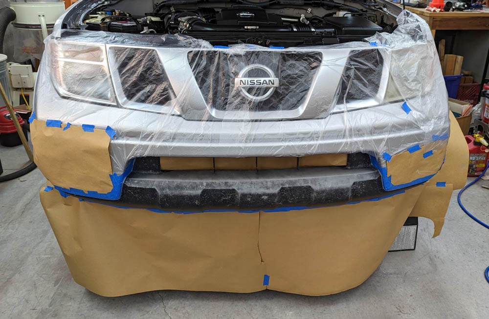
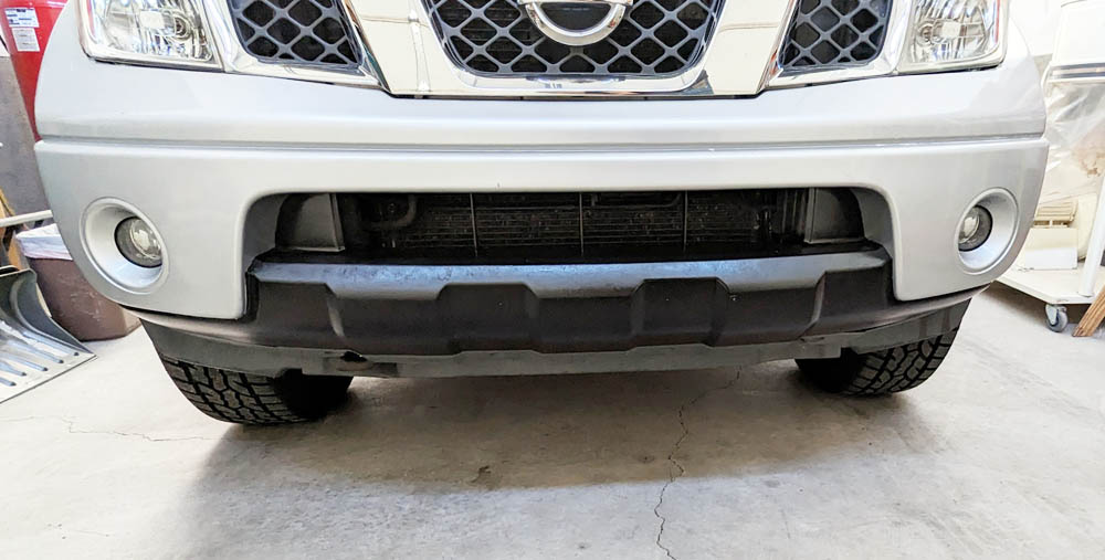
The only hard part about painting the bumper was the masking. Once that was complete, the painting took about 5 minutes per coat for 3 coats. The picture above has a reflection from
the top edge of the bumper. It really is black there also.
Headlight Restoring:
When I bought the truck, the left headlight was quite cloudy, while the right one was clear and shiny. The right was probably replaced several years ago when the truck was involved in a minor fender bender accident of the right front of the truck (the only one CarFax reported during its lifetime). I used my Maguire headlight re-conditioning kit and made both lights shine. The kit has you wet sand the lens with 1000 grit paper, then with 3000, then buff it using a polishing pad in a drill with their polishing compound. The lens is then thoroughly cleaned and coated with 2 coats of the Maguire preservative compound. In addition to protecting the finish, it gives the lens its final sparkle, which is clearer yet than after the polishing.
HomeLink garage door opener:
The truck came with a rear view mirror which is auto-dimming and contains a display of the outdoor temperature and a compass. It also contains a 3 channel HomeLink transmitter. HomeLink is a system used in many automobiles which can be programmed to operate almost all brands of garage door and gate openers. I grabbed the instruction sheet and went through the process of programming a button to my garage door. I could not get it to work through many tries.
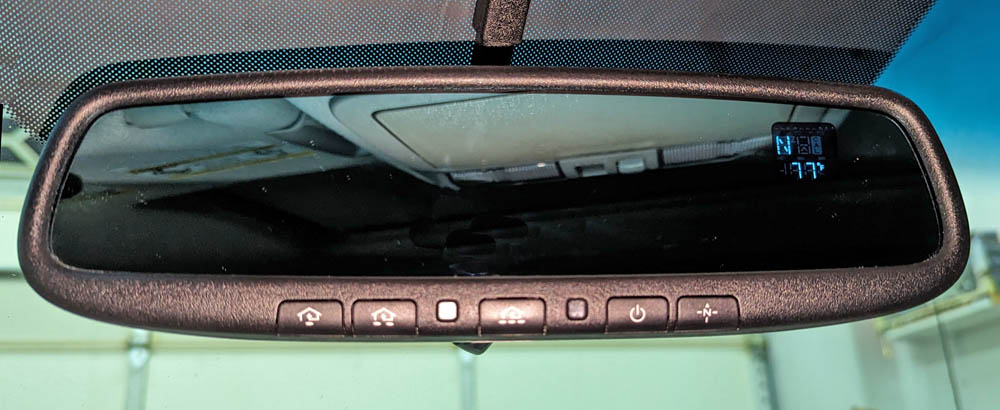
The 3 left hand buttons can control up to 3 different garage door or gate openers. The mirror is auto darkening when bright lights
hit it, and it shows the direction you are driving and the outdoor temperature.
I had read articles showing that older transmitters did not work with the latest openers. I looked up on both the Chamberlain (maker of my garage door opener) and the HomeLink sites. Both sites showed that my car should be compatible with my opener. Then I read an article stating that if your opener has a yellow learn button and a yellow antenna like mine, it is the latest security based system, and will not work with older Homelinks. HomeLink makes a repeater which accepts the signals from old transmitters and re-broadcasts them in the form needed by the new openers. For $40 I bought one, installed it, and all works as it should! I had not tried the RV garage opener as the learn button was on the receiver plugged into a ceiling receptacle 16 feet up. When I had the ladders set up for the Hoister setup, I tried it and it worked from the start. This receiver was installed before my truck was made, so it was natively compatible. To avoid having to climb up in the future to program for another vehicle, I removed the receiver from the ceiling, and plugged it into a wall outlet down low, and ran a wire from it back up to the opener.
The reason the car garage door opener did not work initially was that it was replaced in 2014, and contained the latest security system.
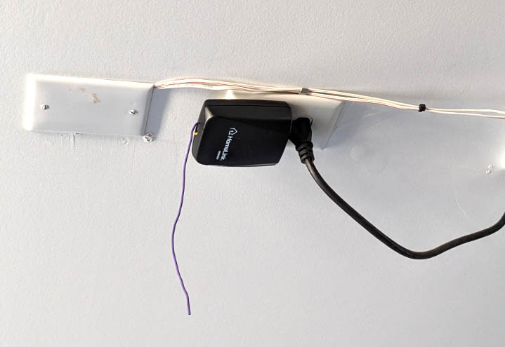
On the left is the repeater. The HomeLink button in the truck sends its signal to this box, which in turn sends the new format signal to the opener. All the previously working transmitters
including the hand held remotes and the Volt (newer) HomeLink continue to talk directly to the opener and work as before. The truck button for the RV garage door works directly with the opener.
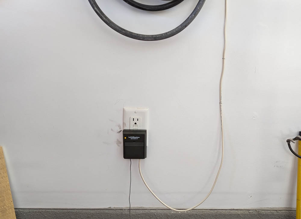
On the right, the receiver for the RV garage is now about 4 feet off the floor - no ladder needed for programming. I think I will install a receptacle somewhat higher to give it a better
signal and to protect it. That is a coiled air hose stored above it and if dropped could shatter the receiver. If I need a step stool or a normal ladder to reach it there is no problem. The problem
before was the need to bring out my 12 foot stepladder, which is a project in itself.