I have now had my Tracker for just
a year, and I have discovered that it is not all that I wanted.
It really has been a fine car which runs well, tows well, and has never
let me down mechanically in any way. I found that I longed for an
automatic transmission more than I had anticipated, and I always had a
nagging feeling that since it is so old that it might fail when I am
far from camp. I also realized that the back seat is very cramped
when I take another couple with us somewhere. During this year, I
have been living in fear that the timing belt might fail since they are
listed as having a 60,000 mile life and the car has over twice that
mileage. I have no record of when or if it has been
replaced. This car has what is called an "interference engine"
which means that if the crankshaft and the camshaft lose the exact
relationship between each other (i.e. broken timing belt) the pistons
and the valves can try to occupy the same space at the same time.
This collision is very expensive to fix! In fact this potential
problem has bothered me so much that I just ordered a timing belt and
water pump kit from Amazon to replace just for my peace of mind.
As it turned out, between the time I placed the order and the time I
received it, I saw a car listed on Craigslist that met all the
requirements I have been casually looking for for over the last several
months.
My New Car
Long story short; Shirley and I drove about 30 miles from here down the mountainous, very curvy section of Hwy 89 going south out of town to the small town of Wilhoit. I seldom see it as it is north of the Kirkland junction where we normally join Hwy 89 after going through Skull Valley and Kirkland. Going that way is slightly longer, but much straighter and is the only way I am willing to take the motor home. Once we got there we looked at a very nice 2004 Suzuki Grand Vitara XL-7, which is a larger version of the regular Grand Vitara, and shortly later I drove it home as the proud new owner with Shirley following me in my Volt! (We came home through Kirkland and Skull Valley!)
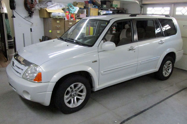
And here is my "new" Suzuki XL-7, which we now call Suzi
My New Car
Long story short; Shirley and I drove about 30 miles from here down the mountainous, very curvy section of Hwy 89 going south out of town to the small town of Wilhoit. I seldom see it as it is north of the Kirkland junction where we normally join Hwy 89 after going through Skull Valley and Kirkland. Going that way is slightly longer, but much straighter and is the only way I am willing to take the motor home. Once we got there we looked at a very nice 2004 Suzuki Grand Vitara XL-7, which is a larger version of the regular Grand Vitara, and shortly later I drove it home as the proud new owner with Shirley following me in my Volt! (We came home through Kirkland and Skull Valley!)
And here is my "new" Suzuki XL-7, which we now call Suzi
Why I picked
this car
I have been watching the ads looking for a car to replaced the Tracker. My want list was for a Suzuki Grand Vitara, which is a direct descendant of the Tracker and still is a full 4 wheel drive vehicle, relatively light weight, and an excellent tow vehicle. I wanted an automatic transmission and a car which was already set up to be towed, preferably using my brand of towbar. Condition and mileage and to a lesser degree, color were all considerations. The towing equipment requirements could vary depending on the price of the car.
This car was for sale by a fellow in Wilhoit who buys this very select type of car and performs whatever mechanical work is needed to assure a trouble free mechanically good vehicle. He has gone though this car and replaced the radiator, water pump, hoses, timing chain, lifters, brakes, etc. along with performing a fresh oil change, transmission fluid change and a thorough check of all other fluids. The car is in very good condition now. In addition it is all set up for towing, and with my brand of towbar! This is a biggie! I had to buy and install the baseplate and all the connections and wiring in the Tracker. That is mostly all done on this car, and the workmanship looks good. I still have to install my own tow car braking system which I have been moving from car to car as I change tow vehicles. I also decided to remount the electrical connector while I mount the braking connections.
So far, I am very well pleased with my purchase.
The Tracker is gone!
When I bought the Suzuki, I was about to replace the timing belt and water pump on the Tracker. I brought the Suzuki home and parked it for several days. I then proceeded to do the mechanical work on the Tracker. It took me a couple days to replace the timing belt, water pump, idler pulley and several smaller items. As it turned out, the timing belt had obviously been replaced in the not too distant past as it was in excellent condition and would have gone on for many more miles. At least now we know the exact status of this belt and know it is good!
After finishing the work on the Tracker, I removed my tow braking system, cleaned up the car and listed it on Craigslist. I was very fortunate and sold it the first day it was listed. It turns out the buyer lives just a few blocks from me. Now I can concentrate on Suzi!
Updating Suzi:
We have a campout starting a little over two weeks from the day I bought Suzi, so my priorities need to start with tailoring the tow equipment for my use. I need to install the braking system, change the electrical connector to the type I use, re-do the mounting for all the connectors, and provide a system for installing the pins that retain the towing brackets. I also need to work out where and how I will attach the safety cables.
The braking system is designed and built in two parts. The first part installs on your air brake equipped motor home and has been in and working for years, starting when I was towing my Subaru. The second part is installed on the tow vehicle and consists of a control box mounted under the hood, an air cylinder mounted under the dash on the brake pedal, and an air hose which couples to the motor home during towing. There are a couple of electrical, vacuum, and air fittings to connect also.
The installation of the braking system was very similar to the 3 previous cars where I have installed it and have written up on this website, so I will not elaborate much here.
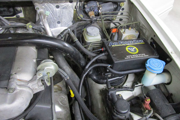
There was a nice open space on the inside of the driver's side fender. There were even pre-threaded holes available to bolt to, so I made a bracket, bolted it in,
attached the control box to it, and made the required connections.
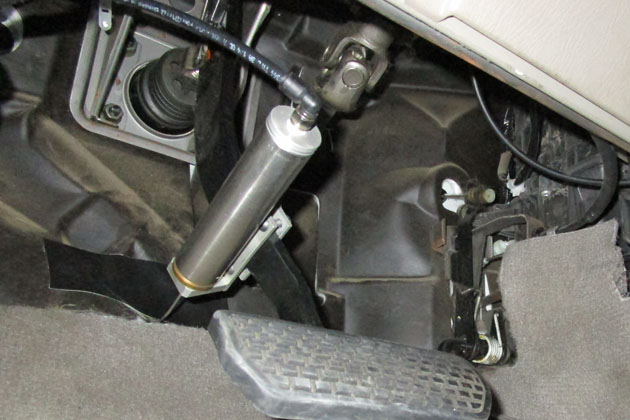
On the right I have mounted the activating cylinder to the brake pedal and connected the pull cable to the floorboard. The black tape is to prevent a tear in the
rubber mat from extending. All of this is out of sight at normal viewing angles.
Towing setup:
Even though the car came equipped for towing, there were several things I needed to do. On the Tracker, there were two wide openings in the area below the grill. The base plate connections to the towbar, along with the connections for the safety cables were in the upper opening and the electrical and braking connections were in the lower. This made life easy, as there was plenty of room.
This car has only one such opening and I need to fit everything into it in a manner that there is room for inserting the retaining pins into the base plate and a method of connecting the safety cables along with the electrical and braking connections. I attacked the problem one item at a time.
First I looked at installing and removing the retaining pins. These insert through part of the base plate and the removable towing arms inside the grill slot and are locked in place with a spring clip where they protrude through the other side. It is pretty tricky holding the pins and getting them to insert into the hole. I solved this by attaching a thin steel handle to the end of the pin with a small hose clamp. This handle allows me to manuever the pin from the outside of the car and insert it into its hole. The clip snaps into place using either a tool I made for the same purpose on the Tracker, or using needle nose pliers. That solved this problem, but still requires a fair amount of free space to do the manipulating. You can see the silver retaining pin in the photo below at the very left opening of the grill, with the handle I added just into the second opening. The loop of the retaining clip just shows at the very left of the first opening.
The standard Roadmaster method of connecting the safety cables is to either connect them to a plate bolted to the front of the removable arms or to extension cables attached to a pair of tabs welded directly to the base plate, again well behind the front of the lower grill opening. Since I want the cables to protect against the greatest number of possible failure points, I ruled out the "easy" front bolted on plate approach. I machined a heavy steel extension and bolted it to the supplied tab. This allows me to clip the safety cable directly to the extension at the front of the grill opening. My first approach was to extend only the tab on the passenger side, as I figured I could clip the other cable directly to the under-bumper tow loop which is on the driver's side. This loop can be seen in the second photo below.
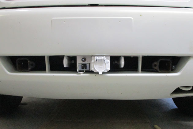
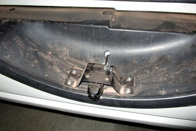
To mount the electrical connector, the breakaway switch, and the air connection for the brakes, I mounted an aluminum plate directly to the frame behind the bumper fascia. Most people just mount directly to the flange of plastic on the fascia resulting in a very flimsy, flexible mounting. I want sturdy, non-flexing mounting which this plate provides. The photo below shows the installation which I used on our first campout towing Suzi. It worked well, but . . .
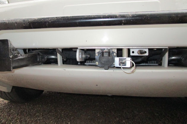
This is the result of my first attempt at setting up the towing system. The breakaway switch is shown in the towing position.
For normal driving, it swings to the side and stores under the air connector. When I actually connected it to the motorhome,
I found that the safety cable did not reach the tow loop under the bumper - I had not properly allowed for the towbar position
during towing. I added a couple of extender loops and all was fine, but it was not ideal.
Our first time towing the car worked very well, but I was not happy with the one safety cable clipping under the bumper, and I felt I could do better. After returning home I did several drawings to see if I could compress things to a size that allowed me to fit the other safety cable bracket into the limited space and still allow clearance where needed. I ended up with a scheme that actually allowed about 3/4 of an inch more than the minimum I needed. Without too much effort I made a bracket which mounted both the air fitting and the front of the breakaway switch, made a second cable bracket, and re-drilled and tapped some holes in the mounting plate.
My final configuration is much cleaner and allows room for both safety cable brackets along with the
needed clearance to install the locking pins and clearance to connect the cables. The factory tow loop
seen under the bumper is no longer used.
Lights:
The car has two dome lights and a couple of map lights up front. All of these were more of an orange glow than real, useful illumination. I had several small LED lights left over from updating the Volt which fit the map lights and the rear dome light. These increased the output a great deal. I also had a dome light consisting of a large array of LEDs - 36 total which I had bought for practically nothing on Ebay for the Tracker, but never used. It was the ideal size to graft onto the original light fixture, so after some thinking and re-thinking I designed and 3D printed a small adapter box which allowed me to take the LED array and mount it on my existing dome light. This puts out a wonderful amount of light and is a good addition.
The other area of the lighting I have improved is the headlights. As received, the lenses of the headlights were just starting to deteriorate into a foggy finish. They were still basically clear, but showing a slight haze. I bought a Maguire restoring kit which includes a very fine sandpaper disk (1000 grit) and an even finer one (3000 grit) and a polishing pad, polish, and a coating to retain the finish. After a session with my electric drill, a spray bottle of water, some microfiber cloths, and some elbow grease, my headlights look factory new.
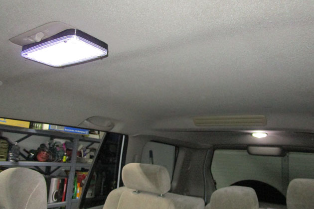
The LED dome lights now provide bright, useful illumination. The map lights (not shown) are equally bright.
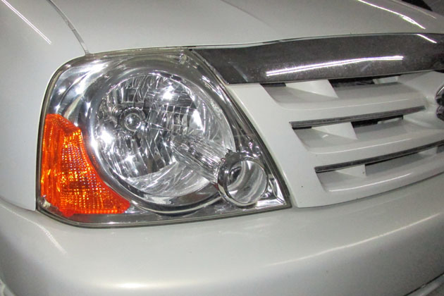
After performing the various sanding and polishing steps, then adding a protective coating, the headlights look factory new!
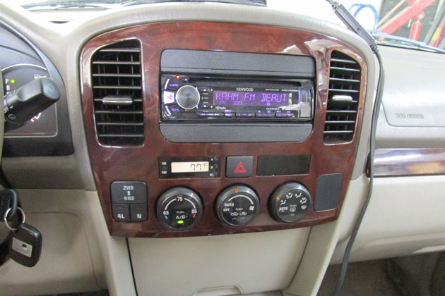
The after market radio that a previous owner installed is a single DIN radio with a couple of ugly filler
panels to fill out the almost 2 DIN opening
Making the mounting bracket turned into a much larger job than I had anticipated. I went to the local scrap yard and found a nice piece of galvanized steel, .040 thick for $2. I looked at several methods of mounting a bracket to the side of the radio where the mounting holes are and to the top where the dash mounts are and finally decided that the most practical is a band around the radio - a box without front or back. After trying to figure how to design something I could then bend into shape and still have it fit, I remembered that I have a portable spot welder which I have not used for a very long time. I dusted it off, resized and refinished the electrodes and tried it on a scrap of my metal. It did a superb job. Now my job was much easier. I cut a strip of metal, bent it into a box shape with overlapping ends and spot welded it. I them made small tabs and spot welded them in the correct locations. This involved a lot of measuring, but was easy to accomplish. The box was a little wider than the radio and if I shimmed the gap, the screw heads would extend wider than the dash opening. I made a super-simple tool consisting of a washer, an aluminum block with a depression machined into it and a pin for alignment. Setting this up around each mounting hole and pressing it in the vise gave me professional looking dimples. Now everything fit and I could mount the radio in the dash.
The wiring harness was fairly simple. The radio came with a harness with many colored wires. I purchased a harness that fit the factory connector in the car and spliced its wires, color for color to the radio harness. Now it was just plug and play. There were several wires that I had to handle separately. Three wires that link to the steering wheel controls, and the wire that senses the backup lights to set the radio to backup camera mode had to be connected individually, as the car harness did not include those wires.
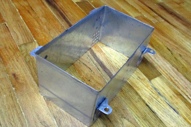
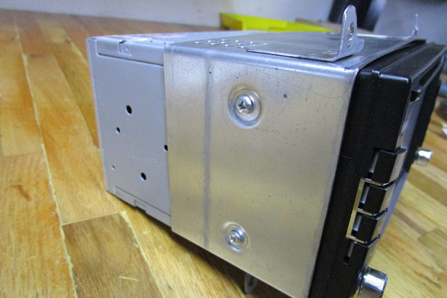
Making the mounting bracket was a LOT of work, but the results were worth it.
The completed radio/bracket combination mounts into the dash cleanly and solidly!
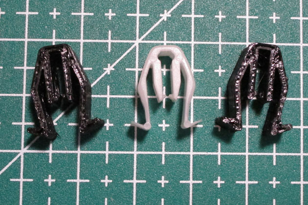
In the process of enlarging the opening in the plastic bezel, I inadvertently destroyed two small plastic clips that allow it to snap into the
dashboard. With my 3D printer coming to the rescue, I was able to make two replacements as shown on the right - and they worked great!
The final installation looks like it was originally designed that way!
I have been watching the ads looking for a car to replaced the Tracker. My want list was for a Suzuki Grand Vitara, which is a direct descendant of the Tracker and still is a full 4 wheel drive vehicle, relatively light weight, and an excellent tow vehicle. I wanted an automatic transmission and a car which was already set up to be towed, preferably using my brand of towbar. Condition and mileage and to a lesser degree, color were all considerations. The towing equipment requirements could vary depending on the price of the car.
This car was for sale by a fellow in Wilhoit who buys this very select type of car and performs whatever mechanical work is needed to assure a trouble free mechanically good vehicle. He has gone though this car and replaced the radiator, water pump, hoses, timing chain, lifters, brakes, etc. along with performing a fresh oil change, transmission fluid change and a thorough check of all other fluids. The car is in very good condition now. In addition it is all set up for towing, and with my brand of towbar! This is a biggie! I had to buy and install the baseplate and all the connections and wiring in the Tracker. That is mostly all done on this car, and the workmanship looks good. I still have to install my own tow car braking system which I have been moving from car to car as I change tow vehicles. I also decided to remount the electrical connector while I mount the braking connections.
So far, I am very well pleased with my purchase.
The Tracker is gone!
When I bought the Suzuki, I was about to replace the timing belt and water pump on the Tracker. I brought the Suzuki home and parked it for several days. I then proceeded to do the mechanical work on the Tracker. It took me a couple days to replace the timing belt, water pump, idler pulley and several smaller items. As it turned out, the timing belt had obviously been replaced in the not too distant past as it was in excellent condition and would have gone on for many more miles. At least now we know the exact status of this belt and know it is good!
After finishing the work on the Tracker, I removed my tow braking system, cleaned up the car and listed it on Craigslist. I was very fortunate and sold it the first day it was listed. It turns out the buyer lives just a few blocks from me. Now I can concentrate on Suzi!
Updating Suzi:
We have a campout starting a little over two weeks from the day I bought Suzi, so my priorities need to start with tailoring the tow equipment for my use. I need to install the braking system, change the electrical connector to the type I use, re-do the mounting for all the connectors, and provide a system for installing the pins that retain the towing brackets. I also need to work out where and how I will attach the safety cables.
The braking system is designed and built in two parts. The first part installs on your air brake equipped motor home and has been in and working for years, starting when I was towing my Subaru. The second part is installed on the tow vehicle and consists of a control box mounted under the hood, an air cylinder mounted under the dash on the brake pedal, and an air hose which couples to the motor home during towing. There are a couple of electrical, vacuum, and air fittings to connect also.
The installation of the braking system was very similar to the 3 previous cars where I have installed it and have written up on this website, so I will not elaborate much here.
There was a nice open space on the inside of the driver's side fender. There were even pre-threaded holes available to bolt to, so I made a bracket, bolted it in,
attached the control box to it, and made the required connections.
On the right I have mounted the activating cylinder to the brake pedal and connected the pull cable to the floorboard. The black tape is to prevent a tear in the
rubber mat from extending. All of this is out of sight at normal viewing angles.
Towing setup:
Even though the car came equipped for towing, there were several things I needed to do. On the Tracker, there were two wide openings in the area below the grill. The base plate connections to the towbar, along with the connections for the safety cables were in the upper opening and the electrical and braking connections were in the lower. This made life easy, as there was plenty of room.
This car has only one such opening and I need to fit everything into it in a manner that there is room for inserting the retaining pins into the base plate and a method of connecting the safety cables along with the electrical and braking connections. I attacked the problem one item at a time.
First I looked at installing and removing the retaining pins. These insert through part of the base plate and the removable towing arms inside the grill slot and are locked in place with a spring clip where they protrude through the other side. It is pretty tricky holding the pins and getting them to insert into the hole. I solved this by attaching a thin steel handle to the end of the pin with a small hose clamp. This handle allows me to manuever the pin from the outside of the car and insert it into its hole. The clip snaps into place using either a tool I made for the same purpose on the Tracker, or using needle nose pliers. That solved this problem, but still requires a fair amount of free space to do the manipulating. You can see the silver retaining pin in the photo below at the very left opening of the grill, with the handle I added just into the second opening. The loop of the retaining clip just shows at the very left of the first opening.
The standard Roadmaster method of connecting the safety cables is to either connect them to a plate bolted to the front of the removable arms or to extension cables attached to a pair of tabs welded directly to the base plate, again well behind the front of the lower grill opening. Since I want the cables to protect against the greatest number of possible failure points, I ruled out the "easy" front bolted on plate approach. I machined a heavy steel extension and bolted it to the supplied tab. This allows me to clip the safety cable directly to the extension at the front of the grill opening. My first approach was to extend only the tab on the passenger side, as I figured I could clip the other cable directly to the under-bumper tow loop which is on the driver's side. This loop can be seen in the second photo below.
To mount the electrical connector, the breakaway switch, and the air connection for the brakes, I mounted an aluminum plate directly to the frame behind the bumper fascia. Most people just mount directly to the flange of plastic on the fascia resulting in a very flimsy, flexible mounting. I want sturdy, non-flexing mounting which this plate provides. The photo below shows the installation which I used on our first campout towing Suzi. It worked well, but . . .
This is the result of my first attempt at setting up the towing system. The breakaway switch is shown in the towing position.
For normal driving, it swings to the side and stores under the air connector. When I actually connected it to the motorhome,
I found that the safety cable did not reach the tow loop under the bumper - I had not properly allowed for the towbar position
during towing. I added a couple of extender loops and all was fine, but it was not ideal.
Our first time towing the car worked very well, but I was not happy with the one safety cable clipping under the bumper, and I felt I could do better. After returning home I did several drawings to see if I could compress things to a size that allowed me to fit the other safety cable bracket into the limited space and still allow clearance where needed. I ended up with a scheme that actually allowed about 3/4 of an inch more than the minimum I needed. Without too much effort I made a bracket which mounted both the air fitting and the front of the breakaway switch, made a second cable bracket, and re-drilled and tapped some holes in the mounting plate.
My final configuration is much cleaner and allows room for both safety cable brackets along with the
needed clearance to install the locking pins and clearance to connect the cables. The factory tow loop
seen under the bumper is no longer used.
Lights:
The car has two dome lights and a couple of map lights up front. All of these were more of an orange glow than real, useful illumination. I had several small LED lights left over from updating the Volt which fit the map lights and the rear dome light. These increased the output a great deal. I also had a dome light consisting of a large array of LEDs - 36 total which I had bought for practically nothing on Ebay for the Tracker, but never used. It was the ideal size to graft onto the original light fixture, so after some thinking and re-thinking I designed and 3D printed a small adapter box which allowed me to take the LED array and mount it on my existing dome light. This puts out a wonderful amount of light and is a good addition.
The other area of the lighting I have improved is the headlights. As received, the lenses of the headlights were just starting to deteriorate into a foggy finish. They were still basically clear, but showing a slight haze. I bought a Maguire restoring kit which includes a very fine sandpaper disk (1000 grit) and an even finer one (3000 grit) and a polishing pad, polish, and a coating to retain the finish. After a session with my electric drill, a spray bottle of water, some microfiber cloths, and some elbow grease, my headlights look factory new.
The LED dome lights now provide bright, useful illumination. The map lights (not shown) are equally bright.
After performing the various sanding and polishing steps, then adding a protective coating, the headlights look factory new!
Backup camera
and radio replacement:
I am a huge fan of backup cameras! I have either added or improved them on every car I have owned during the last 7 or 8 years. Suzi is no exception! Before our first trip, I mounted a camera and ran the wires forward to the dash. This was in preparation for changing the radio to one which could display the camera image, but for now, I temporarily mounted a small monitor below the radio area on the dash. This was really just a proof of concept, and I was impressed with the results.
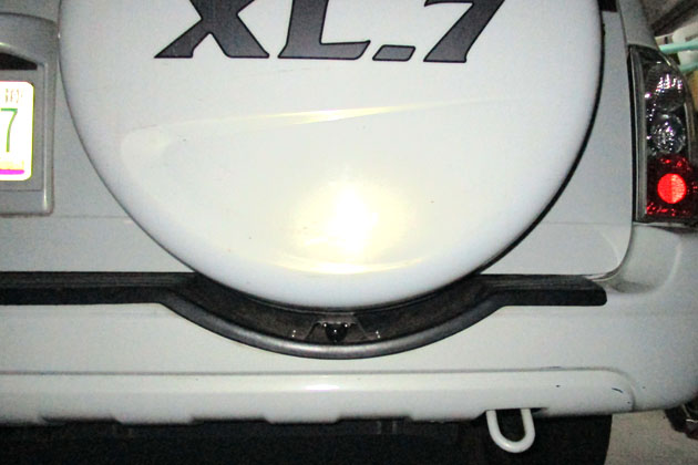
I had a hard time deciding where to mount the camera considering the best viewing location, easiest wire runs, durability, etc. I ended up mounting it on the
bumper below the spare tire. This gives a good view and avoided having to route the wiring through the hinged rear door.
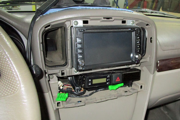
Before I talk about changing the radio let me give a quick description of car radios. With a few exceptions, most car radios fall into one of two size groups. A single DIN radio is about 2 inches high by about 7 inches wide, and for many years was the primary size of car radios. The other standard is a double DIN or 2 DIN radio which is 4 inches high by 7 inches wide. Many cars today use 2 DIN radios with a large touch screen which shows all the radio functions electronically as well as the backup camera images. This is what I want to install in Suzi, but there is a problem: While the basic opening in the dash structure is a full 2 DIN size, the plastic decorative bezel is not. It has curved sides and corners to the opening which will prevent a standard 2 DIN radio from fitting. As a result, all the manufacturers of after market radios state that only a single DIN radio will fit this car, and therefore no one makes the required bracket that adapts a 2 DIN radio to the dash mounting.
After removing the existing radio and checking all the measurements, I decided to purchase a touch screen 2 DIN radio, make my own mounting bracket, and cut out the opening of the bezel to fit. This is a lot more work than the normal 1 to 2 hour installation time should be. I did a lot of research of available radios and selected one from Amazon.
I am a huge fan of backup cameras! I have either added or improved them on every car I have owned during the last 7 or 8 years. Suzi is no exception! Before our first trip, I mounted a camera and ran the wires forward to the dash. This was in preparation for changing the radio to one which could display the camera image, but for now, I temporarily mounted a small monitor below the radio area on the dash. This was really just a proof of concept, and I was impressed with the results.
I had a hard time deciding where to mount the camera considering the best viewing location, easiest wire runs, durability, etc. I ended up mounting it on the
bumper below the spare tire. This gives a good view and avoided having to route the wiring through the hinged rear door.
Before I talk about changing the radio let me give a quick description of car radios. With a few exceptions, most car radios fall into one of two size groups. A single DIN radio is about 2 inches high by about 7 inches wide, and for many years was the primary size of car radios. The other standard is a double DIN or 2 DIN radio which is 4 inches high by 7 inches wide. Many cars today use 2 DIN radios with a large touch screen which shows all the radio functions electronically as well as the backup camera images. This is what I want to install in Suzi, but there is a problem: While the basic opening in the dash structure is a full 2 DIN size, the plastic decorative bezel is not. It has curved sides and corners to the opening which will prevent a standard 2 DIN radio from fitting. As a result, all the manufacturers of after market radios state that only a single DIN radio will fit this car, and therefore no one makes the required bracket that adapts a 2 DIN radio to the dash mounting.
After removing the existing radio and checking all the measurements, I decided to purchase a touch screen 2 DIN radio, make my own mounting bracket, and cut out the opening of the bezel to fit. This is a lot more work than the normal 1 to 2 hour installation time should be. I did a lot of research of available radios and selected one from Amazon.
The after market radio that a previous owner installed is a single DIN radio with a couple of ugly filler
panels to fill out the almost 2 DIN opening
Making the mounting bracket turned into a much larger job than I had anticipated. I went to the local scrap yard and found a nice piece of galvanized steel, .040 thick for $2. I looked at several methods of mounting a bracket to the side of the radio where the mounting holes are and to the top where the dash mounts are and finally decided that the most practical is a band around the radio - a box without front or back. After trying to figure how to design something I could then bend into shape and still have it fit, I remembered that I have a portable spot welder which I have not used for a very long time. I dusted it off, resized and refinished the electrodes and tried it on a scrap of my metal. It did a superb job. Now my job was much easier. I cut a strip of metal, bent it into a box shape with overlapping ends and spot welded it. I them made small tabs and spot welded them in the correct locations. This involved a lot of measuring, but was easy to accomplish. The box was a little wider than the radio and if I shimmed the gap, the screw heads would extend wider than the dash opening. I made a super-simple tool consisting of a washer, an aluminum block with a depression machined into it and a pin for alignment. Setting this up around each mounting hole and pressing it in the vise gave me professional looking dimples. Now everything fit and I could mount the radio in the dash.
The wiring harness was fairly simple. The radio came with a harness with many colored wires. I purchased a harness that fit the factory connector in the car and spliced its wires, color for color to the radio harness. Now it was just plug and play. There were several wires that I had to handle separately. Three wires that link to the steering wheel controls, and the wire that senses the backup lights to set the radio to backup camera mode had to be connected individually, as the car harness did not include those wires.
Making the mounting bracket was a LOT of work, but the results were worth it.
The completed radio/bracket combination mounts into the dash cleanly and solidly!
In the process of enlarging the opening in the plastic bezel, I inadvertently destroyed two small plastic clips that allow it to snap into the
dashboard. With my 3D printer coming to the rescue, I was able to make two replacements as shown on the right - and they worked great!
The final installation looks like it was originally designed that way!
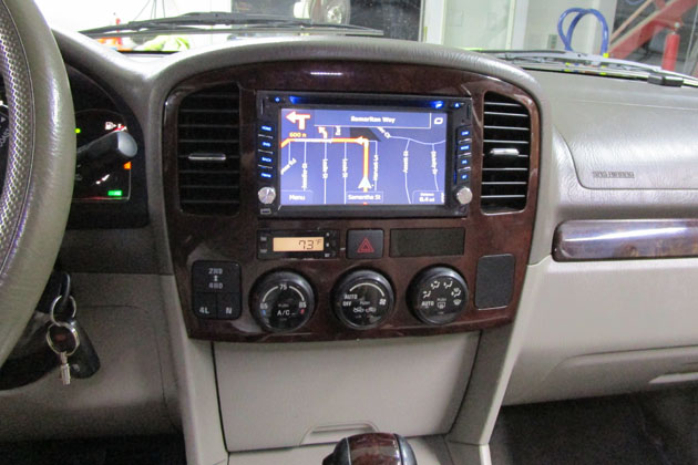
The radio I purchased for a reasonable amount is truly amazing. It has a very good sound and includes
screens for adjusting the equalizer settings and the speaker balance
settings. It includes full GPS navigation, which with the very
little I have used it seems much more intuitive than the one I
installed in the Tracker. It displays the backup camera image
well and it also includes Bluetooth connnections
for both hand free cell phone calls and wireless music from your cell
phone. It includes 2 USB inputs along with micro SD card and 3.5
mm
phone jack inputs, and it will play CDs and DVDs. If it holds up,
it cannot be beat. Time will tell.